As consulting engineers, contractors and building owners seek to control costs and improve the reliability and efficiency of HVAC systems, they must be sure to evaluate all the pros and cons of various systems in order to make the most appropriate selections for their HVAC system design.
A side-by-side comparison of hydronic systems and variable refrigerant flow (VRF) systems is a relevant case in point. Appealing for its ductless technology and claims of superior energy performance, recent studies dispute the effectiveness of VRF, concluding that hydronics outperform VRF in terms of energy performance.
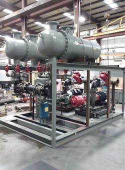
Hydronic systems provide water-based heating and cooling through pipes, ductwork, and other components such as pumps, drives, controls, heat exchangers and valves. VRF systems use refrigerant as their cooling/heating medium and are comprised of a compressor unit connected through refrigerant lines to multiple indoor fan coil or cassette units that are individually controllable by the user.
A 2013 study by Oklahoma State University and Oak Ridge National Laboratory that evaluated the relative performance of geothermal heat pumps versus VRF heating and cooling systems installed at the American Society of Heating Refrigeration and Air-conditioning Engineers (ASHRAE) international headquarters building in Atlanta, found that geothermal heat pumps use 44 percent less energy than VRF systems on an annual basis.
Compared to hydronic systems, VRF systems are expensive in terms of first cost — in many cases between 5 percent and 20 percent higher than hydronic systems due to their complicated refrigerant management system and controls. VRF systems typically require a dedicated outdoor air system to meet ASHRAE 62 ventilation codes, which in many cases adds to the first cost.
Conversely, the initial cost of a hydronic system is generally lower, and these systems offer a much wider range of flexibility for components, operation and maintenance, both in terms of parts and service.
Along with higher first costs, VRF systems generally have a shorter life expectancy than hydronic systems. Hydronic systems have been known to last 20 to 25 years, while VRF systems may need to be replaced as soon as 10 or 15 years after installation. This is because the compressor in a VRF system is forced to work double duty, operating in both heating and cooling cycles. This reduces the life of the compressor.
If air-cooled VRF systems are installed near coastal regions, installers should take special consideration to protect air-cooled condenser coils because the typical life expectancy of these coils with coatings ranges from three to eight years before replacement is needed due to advanced corrosion.
For those who specify HVAC systems for new construction and retrofits, it is important to explore the operational performance and efficiency differences between VRF systems and hydronic systems. Key areas of differentiation are outlined below.
Energy Sources
Hydronic heating and cooling systems are easily adaptable to a variety of current and future energy sources, from natural gas and propane to renewable energy sources such as solar thermal collectors and biomass boilers. In contrast, VRF systems are solely sourced by electricity.
Climate Control
Extremely hot or cold air conditions can impact the performance of both hydronic and VRF systems, though hydronic systems are less affected by temperature changes since the heating and cooling unit is located indoors rather than outdoors. For VRF systems, efficiency is reduced as the ambient temperature goes up in the cooling mode and down in the heating mode.
At lower temperatures, hydronic systems are more reliable than VRF systems because a VRF system may require a supplementary heat source in cold climates, such as electric heat or a hydronic boiler, which could negate the energy efficiency of the system and increase first cost.
A VRF system can provide simultaneous heating and cooling and can recover heat from one zone and use it in another. This is effective in buildings with multiple temperature zones, such as a hotel or school. However, hydronic systems are more practical since they have thermal energy storage capabilities. Water-based hydronic systems can draw the heat or chill out of a room and carry that energy back to the system for storage or recovery, reducing a building’s energy consumption and costs.
Building Scope
When specifying a system, it is important to consider not just building size, but also the size of the system itself. Hydronic systems are better suited to handle buildings requiring 50 to 100 tons of cooling capacity or more. Hydronic systems also have the capacity to pump water efficiently and effectively over long distances, such as across a school campus or through high- and low-rise office buildings.
A VRF system is generally limited to buildings fewer than 10 stories because the length of piping runs must be limited to carry refrigerants and oil through the building in accordance with manufacturer guidelines. Long lengths of piping can jeopardize performance of the unit if oil or refrigerant accumulates in the piping or migrates back to the unit. A larger project could include multiple VRF systems, but that increases costs significantly.
However, for some renovations, like those requiring increased heating or cooling capacity in buildings that are constrained for space, VRF systems may be less expensive than conventional ones. According to an evaluation conducted by the Pacific Northwest National Laboratory, there is a certain subset of buildings to which VRF systems may be particularly well suited.
According to the analysis, existing buildings being considered for VRF should include one or more of the following characteristics:
- Need for HVAC upgrades with limited room for ductwork changes
- Climates with significant heating loads
- Buildings with electric reheat, supplemental heat or primary heating
- 5,000 to 100,000 square feet (larger buildings can be evaluated on a case-by-case basis)
- Buildings with enclosed spaces that would benefit from independent temperature control
Since VRF systems do not need a ducting system within a building to transfer air, they are selected for some specific retrofit situations, particularly in older, smaller buildings with multiple temperature zones. In that regard, VRF systems are a viable option for historic renovation projects, where it is easier and less invasive to install refrigerant piping than larger hot or chilled water piping, along with associated ductwork.
Specialized installation & maintenance
Compared to hydronic water systems that are designed with universal components that can be installed and serviced by any HVAC service technician, VRF systems are proprietary and require specialized technicians for installation and maintenance. This will impact life cycle costs of the VRF system, as building owners will be reliant on the VRF manufacturer for the life of the building.
Components in a hydronic system are factory made and tested, which reduces the rate of failure after installation. In contrast, VRF piping requires mechanical fittings and brazing and soldering on site, so the quality of the installation depends on the level of expertise of the installer. Installers also must be qualified to work with refrigerants under extremely high pressure and be knowledgeable about refrigerant piping locations under their state’s International Mechanical Code (IMC), leak detection, and ventilation requirements per ASHRAE Standard 15.
ASHRAE 15, which has been adopted into the IMC, states the maximum Refrigeration Concentration Limits (RCLs) allowed for a particular space and where refrigerant piping can and cannot be installed. Common restrictions for the installation of refrigerant piping include hallways and large, open areas.
Refrigerant safety
Over the last two decades, refrigerants that contain chlorofluorocarbons (CFCs) and hydrochlorofluorocarbons (HCFCs) such as R-22 have been phased out due to concerns over damage to the ozone layer and global warming potential. Substitute refrigerants such as R-410A are now widely in use, but these hydroflourocarbons (HFCs) have also come under criticism.
In late 2016, the U.S. Environmental Protection Agency updated existing requirements related to ozone-depleting substances such as CFCs and HCFCs and extended them to HFCs like R-410A and R-407C.
The updates, which will take effect on Jan. 1, 2019, include:
- More stringent requirements for repairing leaks in larger appliances
- New record keeping for the disposal of appliances containing 5 to 50 pounds of refrigerant
- New reporting requirements for chronically leaking appliances, which include mandatory leak checks for leaks more than 10 percent of the system charge
- Restricting the sale of HFC refrigerant to technicians certified under Sections 608 or 609 of the Clean Air Act
Although a leak can develop in both hydronic systems and VRF systems, a leak in a VRF system is a serious and potentially dangerous matter. Refrigerant leaks can be hard to find and difficult to repair because they are not detectable by sight or smell. Refrigerants are heavier than air, and if a leak develops, the accumulation of refrigerant will displace the air in the room. In spaces with minimal ventilation, it is possible for refrigerant concentrations to reach values that put people at risk of losing consciousness and even suffocation.
Under the U.S. Environmental Protection Agency’s (EPA) updated refrigerant management requirements, owners or operators must calculate the leak rate every time substitute refrigerant is added to an appliance (unless the addition is made immediately following a retrofit, installation of a new appliance or qualifies as a seasonal variance).
The final rule also includes the following provisions for owners and operators of refrigeration and airconditioning systems:
- Quarterly or annual leak inspections or continuous monitoring devices for refrigeration and air conditioning equipment that has exceeded the threshold leak rate of 10 percent total refrigerate charge annually
- Owners or operators must submit reports to the EPA if systems containing 50 or more pounds of refrigerant leak 125 percent or more of their full charge in one calendar year and repair leaks that exceed 10 percent in comfort cooling equipment within 30 days of detecting the leak
- Sales restriction extended to HFCs and other non-exempt substitutes, with the exception of small cans (containing 2 pounds or less) of nonexempt substitutes for motor vehicle air conditioner servicing
- Technicians required to keep a record of refrigerant recovered during system disposal from systems with a 5- to 50-pound charge size
Fit for the future
Hydronic systems will continue to be the dominant HVAC technology because they enable engineers, architects, contractors and building owners to adapt to changing demands.
The concept of a net-zero energy building, one that produces as much energy as it consumes during the course of a year, is being modeled in a few select projects, but it will soon be the norm as governments worldwide — from the U.S. to Europe to Japan — set into place net-zero standards for new public buildings between 2020 and 2030. Hydronic heating and cooling systems will continue to be the most efficient solutions over time in terms of cost, performance and efficiency.
Kyle DelPiano is a market development manager, southeast territory, at Xylem Inc. He is an active ASHRAE member and is LEED AP certified.


