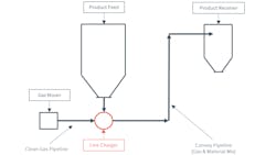
A simple pneumatic conveying system is comprised of five main components: the gas mover, the product feed, the line charger, the pipeline, and the product receiver (Figure 1). The line charger has a very critical role: it needs to charge the convey line at a metered rate while minimizing the escape of pressurized gas (in positive pressure systems). In this application, the line charger is serving as both a feeder and an airlock.
Pneumatic conveying systems use several different types of line chargers. Depending on the application, one might be a better choice than others. By understanding the differences between the different line charger types, you can make an informed decision about which line charger to select for your system. Selecting a wrong line charger for your system can cause many problems, such as:
- Accelerated line charger wear, which can lead to unplanned system shutdowns, extra operating costs or excessive gas leakage.
- Excessive gas leakage, which can lead to reduced system capacity, plugging in the pipeline or excessive dust emissions.
- Bridging/arching of material above the line charger feed point, which causes convey line material starving or intermittent feed.
Before looking at the different line charger types, it is important to settle a widely held misconception. While it is true that some types of line chargers are most commonly used in either dilute phase or dense phase systems, the line charger does not dictate the mode of conveying in the pipeline once the material is mixed with gas. The material-to-gas ratio and the velocity of the material in the pipeline in relation to the material’s saltation velocity dictate whether the material will be transported in dilute or dense phase. Also, dense phase conveying usually requires a high gas pressure, and since some types of line chargers have limited pressure differential ratings, they are not typically associated with dense phase conveying.
The mode of conveying is typically one of the first decisions made with regard to system design, with decisions such as the best line charger made subsequently.
Types of line chargers
The following is a list of the main line charger types used in the industry. Please note that many variations of each type exist, and it would be difficult to execute a summary of all of them in a single article.
Rotary airlocks
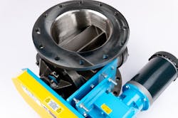
Rotary airlocks (Figure 2) are the workhorses of the industry as they are simple, compact and widely available. They can provide an almost continuous product feed, as the pocket discharge cycle rate is short compared to other line chargers.
Rotary airlocks are not typically recommended for use with coarse and/or very abrasive materials, as the internals can wear out rapidly. However, versions are available that include various forms of abrasion resistance to extend the component’s life.
Rotary airlocks have a limited pressure differential rating since there is a gap between the rotor blade and the casing. This is why they are usually used for dilute phase systems at low to medium pressure differentials. Some specialized models can handle higher pressure and can be used as line chargers for continuous dense phase or high-pressure dilute phase systems, for low-abrasion applications.
Double dump valves
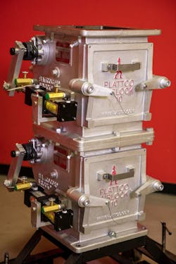
Double dump valves consist of two valves positioned one on top of the other and separated by an accumulation chamber (Figure 3). The valves open alternatively in cycle, allowing material to pass through while keeping gas updraft to a minimum. The valves are never opened simultaneously. Different types of valves can be used depending on the application, such as flapper valves, ball valves, slide gates, spherical valves, and others.
Double dump valves can handle high-temperature applications. Some models allow gravimetric feed of material with load cells positioned on the accumulation chamber. Since double dump valves don’t provide a continuous discharge (long material discharge cycle rate), they are usually not used in dense phase systems.
Blow tanks
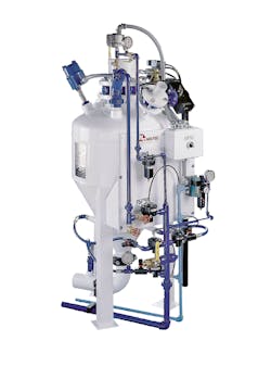
A blow tank (Figure 4) is basically a pressure vessel used to push material inside the convey pipeline. It is equipped with many monitoring devices and instruments to optimize the material discharge cycle.
Once the bottom valve on the blow tank is opened, it stays open until all the material is fed into the convey pipeline. Blow tanks are not discharged by gravity; the pressure differential inside the tank helps to push the material out. Some models are equipped with fluidizing air to help difficult, less free-flowing materials flow.
Blow tanks have a long cycle time and can’t be filled during their pressurization and discharge cycle. For this reason, if the process upstream requires a continuous material flow, two blow tanks are used, with one being filled while the other is discharging material into the pipeline. Alternatively, an intermediate hopper above the blow tank can be used as a holding tank to receive the continuous process discharge while the pressure tank below is in the discharge cycle.
Blow tanks are designed to operate at higher pressure differentials and provide a high material to gas ratio. For this reason, they are most often used in dense phase systems. They can however be used in dilute phase systems if a higher pressure is required for the application or when handling extremely abrasive materials.
Screw pumps
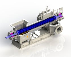
A screw pump (Figure 5) is basically a heavy-duty screw feeder with the pitch of the screw diminishing between the material inlet flange and the screw discharge. This diminution in screw pitch compresses the material and creates a gas seal between the low-pressure screw inlet and the high-pressure screw discharge. Screw pumps are equipped with a non-return valve at their discharge end that closes when no material is in the screw to prevent gas leakage.
A screw pump’s seal quality is highly dependent on the bulk material properties, and they are therefore generally recommended only for free-flowing materials with a small mean particle size. With the right bulk materials, high pressure seals can be obtained, and screw pumps can be used in dense phase systems. Screw pumps are not recommended for extremely abrasive materials.
Eductors
Eductors create a vacuum at their inlet throat from a positive pressure airflow using the Venturi effect. This vacuum charges the eductor with bulk material, which is then mixed with the airflow in a pressure pneumatic conveyor.
Eductors basically solve the problems associated with line charger air leakage in pressure systems. They are small and compact as well as reliable, since they have no moving parts.
Eductors must be used with free-flowing materials and are limited to low-capacity/low-pressure systems. They provide low flexibility for flow rate control. For this reason, they can be coupled with a metering device upstream if an accurate control is required.
Eductors generate a high-pressure differential, meaning that the total system pressure will be higher than with other line chargers.
Lock hoppers
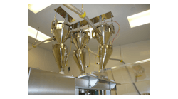
Lock hoppers are in a class of their own as they are not line chargers per se but can be used in conjunction with other line chargers to achieve an optimized solution when applicable. Lock hoppers are accumulation hoppers with an isolation gate at their inlet flange and a line charger at their discharge flange. Once the lock hopper is filled with material, the inlet valve closes to isolate the upstream equipment from the convey pipeline pressure. This keeps the line charger at the lock hopper’s discharge from being exposed to a pressure differential. Only the lock hopper inlet valve is exposed to the pressure differential. Lock hoppers, therefore, eliminate the pressure differential to which virtually any line charger can be exposed, expanding the range of convey line pressures they can operate in.
Individual lock hoppers do not operate continuously but in batches. Therefore, if the upstream process requires continuous operation, two lock hoppers are required, with one being filled while the other is discharged into the pneumatic conveyor downstream. Dual lock hoppers can be positioned on top of each other to reduce the total required footprint. In this configuration, a single line charger is used.
Suction nozzles
Suction nozzles are applicable only to vacuum conveying systems. They are basically the air intake side of the convey pipeline in a vacuum system that is used to suck material. It is very similar to a domestic vacuum cleaner. The main difference is the ability to adjust the air intake near the material intake to control the material flow. There are also additional air intakes on the suction arm, downstream of the material intake that prevent the line from being choked and plugged.
Suction nozzles are generally manually operated to suck material from a bag or a box, but they can also be used on larger scales to empty trucks, containers or ships. Since these line chargers are used on vacuum systems, which have a limitation in negative pressure (less than one atmosphere of vacuum), they are usually seen on dilute systems.
Flood fed
Flood fed line chargers are also only used on vacuum systems. This concept is similar to a suction nozzle in that a pipe under vacuum is connected to the discharge of a hopper. A partially opened slide gate can be used to help meter the material flow rate. Additional air intakes on the convey pipeline, downstream of the material pickup point, prevents line plugging by ensuring that the correct rate of air flow is available.
Selecting a line charger
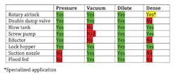
Table 1 can be used as a guide for selecting the right line charger for the application. The table lists which line chargers are best suited for a given system conveying mode and phase.
Colin Barbeau is Eastern North America bulk materials handling lead at Hatch and a member of Processing’s editorial advisory board. He can be reached at [email protected].
Hatch
www.hatch.com
