Rotary airlock valves are key, but often underappreciated, components in many dry bulk solids applications. A malfunctioning rotary airlock valve can reduce a system’s operating efficiency or stop production entirely.
A rotary airlock valve is designed to control the flow of bulk solids from one process to another, many times while maintaining a pressure differential. For example, one common use is to deliver bulk solids from a storage vessel or silo into a pneumatic conveying circuit. In this case, the rotary airlock valve is critical to maintaining the pressure within the circuit while controlling the rate of bulk solids flow into it.
In another example, the rotary airlock valve may be used to seal the discharge of cyclones or baghouses used for material and air separation at the termination of pneumatic circuits. Here, the airlock maintains the efficiency of the cyclone or baghouse by preventing air leakage while discharging bulk solids. Also, they are often a key part of NFPA compliance as a flame isolation barrier, preventing the passage of flames from a cyclone or baghouse in the event of a deflagration.
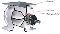
The design and function of a rotary airlock valve is simple. It consists of a housing with end plates inside of which is a multi-vane rotor with six or more pockets designed to hold the bulk solid material (Figure 1). As the rotor turns, material fills the pockets at the inlet then discharges at the bottom. Empty pockets return to the inlet and begin the process over again. The end plates contain bearings to support the rotor and seals to prevent the discharge of material as the rotor turns.
When selecting a rotary airlock valve for a specific application, it is important to consider the following five factors, which will influence the valve’s design. While these five topics are not the only factors that may go into specifying a rotary airlock valve, they serve as good foundation of research when preparing to speak with prospective vendors.
1. Displacement
Displacement is the volume of material moved or transferred from point A to point B per unit of time. In many cases, this is expressed in cubic feet per revolution (CFR). An airlock’s CFR is a basic unit of measurement that is easily scaled to determine how large an airlock is needed to move an amount of material.
When considering the displacement of a rotary valve, be aware of the following:
Fill factor. Most equipment manufacturers state airlock displacement with a fill factor applied. Fill factor is how full the pockets will be compared to calculated rotor volume. Due to the flow properties of most bulk solid materials, a rotor will never fill 100%. In many cases, valve displacement is stated at 80% fill factor, although process-related conditions can increase or decrease this value. The proper fill factor is essential to displacing the required amount of material.
RPM and vane pass frequency. When an airlock is flood fed under a bulk tank or silo, material must flow into the rotor to achieve the stated fill factor. The rotor RPM will dictate how much time each pocket spends exposed to the inlet for filling. While in most cases this is not a factor, materials with poor flow characteristics or applications with high RPM requirements could reduce the fill factor. At very high RPMs, the additional displacement could be offset by the reduction in fill factor.
Inlet throat size. Whereas the nominal opening of an airlock is its dimension at the flange, throat size is the effective width of the opening where it necks down to meet the rotor (Figure 2). A wider throat will provide more time for the rotor pockets to fill, even at higher RPMs.
Metering function. For some applications, the airlock valve may need to provide a specific and uniform flow to a critical piece of equipment. In this case, that equipment may be sensitive to fluctuations in material flow. Given their design, airlocks deliver a “pulse” of material for each rotor pocket. For a slow turning valve — say 5 RPM — the pulses are 40 per minute, or one every 1.5 seconds. Essentially, for a turning airlock, the material delivery is turned on and off with each pulse. When uniform flow is critical, choose an airlock that will rotate faster than 10 RPM, preferably 15. In cases where that is not possible, explore the following two rotor options:
- Reduced-pocket rotors. A reduced-pocket rotor design permanently fills in a portion of the airlock rotor pocket, resulting in lower CFR (Figure 3, left). This will allow the airlock to run at higher RPM while preventing it from overfeeding the critical component.
- Split-pocket rotors. Primarily used in feeding applications, with a split-pocket rotor, the pocket length is bisected into two or more sets of blades that are offset from one another. This results in smaller, more frequent pulses per revolution (Figure 3, right).
2. Pressure differential
After displacement, the next most important airlock function is to maintain a pressure differential. In the case of a rotary airlock valve displacing bulk solids from a storage silo into a pressurized pneumatic circuit, it is imperative that the pressure be maintained in the system for the purpose of conveying the bulk material. If the airlock is built with large clearances or if it is overcompensated for thermal expansion (next topic), the system will leak. This will result in higher operating costs and the potential for costly downtime to clean a plugged pneumatic conveying line. Leakage air can also disrupt the flow of material into the airlock, reducing fill factor and displacement efficiency.
3. Temperature compensation
Processes with hot material or heated process air or conveying air can affect an airlock’s operating temperature. As the airlock is exposed to temperature, the rotor will expand differently than the body, resulting in a change to its operating clearances. In this case, it is imperative that the rotor be properly compensated for thermal expansion to maintain its design clearance at temperature. An undercompensated rotor may overexpand, which can cause the airlock to squeal or seize. An overcompensated rotor will result in larger operating gaps that could reduce the airlock’s effectiveness as an air seal. It is good practice to review your application for any temperature variances and be sure to specify these to the vendor.
4. Bulk material properties
Bulk material properties play a role in several rotary airlock valve design criteria:
Flowability. How fluid is the material? How well will it flow into the airlock pockets? As discussed in the first topic, poorly flowing materials can reduce fill factor and airlock displacement if airlock size and RPM are not factored properly. Conversely, very fine, highly fluidized materials can flush around the rotor vanes, so vane clearances should be minimized.
Cohesiveness. Is the material sticky? Does it tend to pack? These attributes can affect how well the material discharges from the rotor. Cohesive materials can reduce the displacement of an airlock, so an anti-friction coating of the pockets should be considered. For airlocks charging a non-abrasive material into a conveying line, one option is to use a blow-through airlock. In this design, the conveying air passes directly through the rotor to evacuate material (Figure 4).
Abrasiveness. A worn valve will leak material or not function as an effective air seal. When specifying an airlock to handle an abrasive material, be sure to review options to coat the housing and rotor vanes with a harder, longer-lasting material that will provide an acceptable amount of operating life. Often, the additional cost of the wear coating will pay for itself with a greater duty cycle and longer intervals between downtime for maintenance and repairs.
Fineness. Fine materials can migrate past shaft seals, resulting in a leak, particularly when the airlock is connected to a pressurized conveying system. Many manufacturers offer a variety of seal options or purge systems to improve the life of seals in these applications.
5. Environment
The operating environment inside and around the airlock should be considered for several reasons:
Operating temperature. Properly compensating the airlock rotor for thermal expansion has already been discussed, but for highly elevated temperatures, also consider the design of the bearings, seals and drive components to ensure that they are compatible.
Corrosion. Airlocks that handle corrosive materials or salts or that operate in tropical environments should be manufactured from corrosion-resistant materials, such as stainless steel.
Humidity/moisture. Airlocks that are installed in humid environments, such as outdoor coastal areas or in plants with wet processes should likewise be built from corrosion-resistant materials. In addition, it may be necessary to specify higher-grade or washdown-rated electrical devices and motors. Seek out a chart on NEMA enclosure ratings or ingress protection (IP) ratings for options available for devices such as solenoids, door limit switches and drives/motors.
Darrell Malczewski is the Midwest regional sales manager for Prater Industries, a leading global supplier of airlocks, size reduction and screening/separation equipment. His 25 years of bulk material handling experience include various roles with Prater, including test lab manager, technical field services, airlock product manager and, currently, regional sales.
Prater Industries
www.prater.com


