By Arsalan Ahmed, Vertical Marketing Manager, Crane ChemPharma & Energy
Ethylene — one of the most in-demand olefins in today’s petrochemical markets — in production yields a generous menu of downstream products that include acetates, alcohols, benzenes and polymers. About 60 percent of global ethylene production is used to produce types of polyethylene, converted into daily-use items such as plastic bags, pipes and composite films.
Ethylene economics are driven by socio-economic developments, energy prices and product yields. Global demand rose from 250 billion pounds per year in 2008 to more than 300 billion pounds in 2015, and growth is expected to continue for at least the next five years.
Productive capacity utilization will remain more than 85 percent, even during the crude-oil crises. With the recent shale revolution, the North American market is expected to account for about 24 percent of global ethylene production by 2020. To meet global demand, two or three new ethylene plants must be built annually in North America, and in the Middle East and Asia Pacific.
Ethylene production comprises four major steps: cracking, quenching, compression and processing. For each, shut-off valves play an essential role in maximizing ethylene quality and output yield, as they ensure the appropriate ratio of feedstock and output products. Failure to comply with requirements and standards may lead to unwarranted emissions, damages or shutdowns.
In describing ethylene production we can summarize how various valve designs address challenges inherent to ethylene production and suggest how appropriate fluid-handling equipment can be sized and selected.
Cracking & quenching
During cracking, also called pyrolysis, the feedstock hydrocarbon is almost quite literally "cracked," or broken down, into several components, under high temperature (1300-1700 F) and pressures.
Two major ethylene feedstocks are naphtha and natural gas, including ethane, propane, butane and others. Naphtha is a liquid hydrocarbon mixture derived from crude oil, coal tar or shale deposits. Natural gas is a mix of hydrocarbons extracted from shale, petroleum and coal deposits.
Feedstock is cracked using steam, thermal and catalytic methods.
Feedstock is pumped into a furnace chamber in the presence of fuel and steam, and heated to around 1560 F, at 23 psi. Added steam reduces hydrocarbon partial pressure and increases olefin yield. Under these conditions, the hydrocarbon cracks into smaller molecules.
Next, decoking effluent is routed through decoking lines where coke fines are separated from the cracked gases. Decoking valves must withstand high temperature and pressure conditions and be capable of 100 percent tight shutoff to prevent leakage. Leaving the furnace, product mixture enters the quench towers and immediately cooled from 850 F to 340 F to maintain gas composition.
This rapid cooling is called quenching. In this case, it is a two-step process, with fluid passing first through oil and then water. Oil helps remove remaining coke particles; water acts as backup cooling, to ensure adequate gas cooling.
In ethylene production, highly erosive fluids expose quench towers to high risks of failure. Due to extreme temperature and pressures, equipment must withstand a volatile environment and perform efficiently. Cracking is a critical step and extreme caution is exerted to protect equipment from harsh conditions or such things as sudden back-pressure drop.
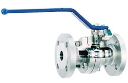
The various valves
Cracker-unit valve selection plays a critical role in maximizing quality ethylene output. Several valves are involved in obtaining the appropriate input ratio of inputs. Check valves ensure backflow protection. The point is to restrict coke build-up and inline leakage.
Wedge-plug valves play a valued role along the cracker lines in the furnace unit, as they have been developed to accommodate challenging media like naphtha feedstock. They can eliminate operational issues caused by coke contamination and build-up within the valve.
In addition to simple, rugged, inline-repairable design, a wedge-plug’s multiple boss locations mean a variety of purge options preclude process-media from entering valve cavities to cause coking issues. Moreover, the unique lift-and-turn operation of wedge-plug valves enables the valve to operate with virtually no rubbing or contact of the seats and plug, to reduce wear and extend valve life.
Other factors, like materials composition and coatings, are also considerations when selecting valves for the cracking stage of ethylene production. In such high-temperature settings, for example, valves with graphite packing are an ideal solution compared to PTFE-packed alternatives. Likewise, the recommended body material is WC9 with Fire safe API 600, 607, Emissions API 624, ISO 15848, Class V seat leakage, and typical coatings include hard chromium, tungsten carbide, nickel boron. Finally, noise abatement trim can help reduce noise and vibration during operation.
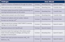
Critical cracking and quenching challenges and affected process areas are outlined in Table 1.
Compression & caustic scrubbing
After cracking, cooled hydrocarbons are compressed and cleaned of waste before being separated into constituent products. During compression, pressures reach as high as 520 psi in a four- or five-stage centrifugal compressor that removes toxins and impurities.
Each compressor has two or three compressor casings driven by an extraction/condensing turbine. Compression is in four stages, with pressures ranging from 21 psi (1.5 bar) to 522 psi (36 bar) at the end of the fourth stage. A bypass prevents back-pressure drop due to pressure difference between compressor inlets and outlets.
A subsequent cleaning process, called caustic scrubbing, occurs as compressed gas enters the caustic towers, and undergoes sequential scrubbing to remove acid gases (acetic acid), hydrogen sulfide (H2S) and carbon dioxide (CO2).
Between stages, water and hydrocarbons are separated from the pyrolysis gas and recycled.
The resulting oscillation of gas pressure can cause compressors to become instable at inlet and outlet, leading to noise, known as surging, potentially damaging equipment. To avoid this possibility, a bypass valve is installed between the compressor inlet and outlet.
In this environment, the valve should be able to throttle from zero to 100 percent to prevent flow reversal. To protect the compressor from damaging backflow, a critical check valve is located on the compressor’s discharge line. Damage to compressor units can lead to several hundred thousand dollars in repair cost and production loss.
Axial flow nozzle-type check valves have advantages here, as their non-slamming design ensures the lowest pressure drop across the valve, a significant benefit when it comes to minimizing pressure loss in piping systems.
Critical challenges in compression and caustic scrubbing and affected process areas are outlined in Table 2.
Valve-body materials should also be evaluated to ensure best performance in severe service. The recommended body material for valves utilized in compression is WC9 with Fire safe API 600, 607, Emissions API 624, ISO 15848, with Class V seat leakage. Noise attenuation trim is also recommended to reduce noise and vibration. Furthermore, valves should be equipped with actuators to quickly react to surge conditions. In general, full-port-design ball valves are generally preferred to butterfly designs.
Drying & fractionation
During the third stage, compressed gas is dried and separated into individual sub-products, including methane, ethane and propylene, as well as ethylene.
To prevent ice particles from forming and causing abrasion to equipment, it is essential to remove all water from the gas during the fractionating process. Complete removal of water is achieved with the molecular sieve dryers — one dryer typically is in normal operation while the other is being regenerated.
Drying is done by adsorption, i.e., the adhesion to porous materials that creates a layer on top of the adsorbent, or desiccant. Operating at semi-cryogenic temperatures, desiccant inside the dryer causes vapors to condense on its surface, taking water out of the system. Once the desiccant is fully saturated, the dryer is regenerated by passing steam or hydrocarbons to remove water from the dryer. Should a dryer fail, the plant is susceptible to shut-down.
Because of this, flawless valve shutoff within the drying unit is essential to prevent inline leakage and improved bed drying. Sealing must be strong enough to overcome wear due to adsorption beads and fines, and valves must incorporate high-cycle and set-point requirements to improve process efficiency.
Critical challenges of drying and affected process areas are outlined in Table 3.
During fractionation, dried gas enters the fractionation columns at cryogenic temperatures (-40 C, 32 bar) and undergoes multiple fractionation stages that separate the gas into different hydrocarbons.
The demethanizer completes the separation of methane (also called C1) from ethylene and heavier components, operating at around -142 C, 880kPa. Demethanizer overhead consists of methane, with some minor impurities of hydrogen, carbon monoxide, and traces of ethylene. Brazed aluminum plate-fin exchangers are used for the multi-pass cryogenic heat-transfer services, installed in a cylindrical or rectangular carbon-steel container, commonly known as a cold box. This unit is filled with perlite or rock wool for insulation. Meanwhile, hydrogen is removed during the process.
Once methane has been separated, heavier components containing ethylene and ethane (C2) are passed on to the De-ethanizer column. Here, as much ethane is separated as possible.
Heavier hydrocarbons in the chain are moved to the next stage of distillation. The bottoms of the de-ethanizer are moved into the de-propanizer, which separates propane (C3) from heavier olefins C4+.
Heavier olefins exiting the bottom of the de-propanizer enter the de-butanizer, the last fractionator in the series, responsible for producing butane (C4).
The end product
The end product, ethylene, must not contain any acetylene, which can contaminate polymer production. It becomes ethylene inside the converter, which contains 4-6 reactors and through the hydrogenation process, where hydrogen is used to convert the gas into ethylene. Since the reaction is exothermic and contains hydrogen, control of temperature is very important in valve selection.
Any remaining acetylene is converted into ethylene at cryogenic temperatures and high pressure to produce high-purity ethylene and ethane gas in the ethylene fractionator, designed so that vapors can rise and condensate can drain.
As hydrocarbon vapors feed into the chamber, they rise until they condense and collect on trays. If they drain down, they re-vaporize and rise again. Distillation essentially separates the hydrocarbons into different yield streams such as ethylene and propylene.
With numerous product lines and associated pumps running from the fractionator, several opportunities present themselves for use of highly-engineered dual-plate and nozzle-style check valves, triple-offset butterfly valves and cast-steel gate valves. Check valves protect pumps. Triple offset butterfly and cast-steel gate valves are used in isolation applications, with the former used to isolate in the lighter product lines such as naphtha & gasoline and the latter used in heavier product lines.
Other important valve considerations include bi-directional sealing capability to allow isolation from both directions for reverse-flow issues. Also, due to the high risk of cavitation, Class VI shutoff is required.
Critical challenges of fractionation and affected process areas are outlined in the Table 4.
Final words
As the petrochemical industry faces increasing challenges, ever-enhanced efficiency fuels the next generation of olefin production. Valves must address the specific conditions of the changing environment. Valve users require solutions that are safe, reliable and engineered to meet global demands. In valve selection, consider the pluses and the minuses, and work with a proven manufacturer to ensure valve equipment addresses the needs of next-generation of ethylene and other type process-industry plants.


