Control valve sizing and selection for continuous process operations
Process plant operations involve many rigorous tasks requiring the highest level of measurement and control performance. Control valve technology, in particular, plays a vital role in production processes. Valves are the most important single element in any fluid handling system because they regulate the flow of fluid to the process.
This article describes the importance of proper control valve sizing and selection to manufacturing efficiency, reliability, quality and safety. When choosing a valve to meet a specific application requirement, and considering key factors such as sizing and trim materials, it is wise to consult with a qualified valve engineer capable of analyzing the application to ensure that the right device is chosen and deployed appropriately.
Background
Process industry manufacturers are trying to stay on top of industry changes more than ever — maintaining utmost product quality and meeting and exceeding increasingly stringent safety regulations are just two of the challenges they face. They must implement effective manufacturing techniques, which are cost-efficient, time-saving and reliable.
Control valves are employed in many different ways in a typical plant. They are controlled devices that regulate the flow of a liquid or gas in a system. The varying resistance that the valve introduces into the system as it is stroked accomplishes this regulation. As the valve modulates to the closed position, the system pressure drop shifts to the valve and reduces the flow in the system (See Image 2).
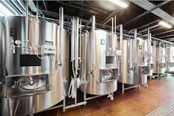
Image 2. Control valves play a crucial part in complex process plant operations.
Modern control valve designs allow them to be used simply as an on-and-off device, or for any combination of controlling to include regulation, modulation, mixing or even isolation. They are a highly engineered product and should not be treated simply as a commodity. Addressing control valve performance has a dramatic effect on process plant efficiency, overall profitability and asset life cycle costs.
Need for proper valve sizing
When engineers talk about control valve sizing, they generally refer to the entire process of selecting equipment that will provide an optimal solution for a specified measurement and control function. Indeed, choosing a properly sized valve is essential to achieving the highest degree of control for the liquid, gas or multiphase fluid.
The style of control valve is usually determined by the user’s requirements, past experiences or plant preference. Valve selection can be a tricky process, but sizing the valve can be even more difficult. Valves are often incorrectly specified at the time of installation.
The most important variables to consider when sizing a valve include:
- What medium will the valve control?
- What effects will specific gravity and viscosity have on the valve size?
- What will the inlet pressure be under maximum load demand? What is the inlet temperature?
- What pressure drop (differential) will exist across the valve under maximum load demand?
- What maximum capacity should the valve handle?
- What is the maximum pressure differential for closing the valve?
The required flow rate the valve must pass and the pressure drop that can be allowed across the instrument typically govern its sizing for a particular duty. For example, an undersized valve does not have the capacity to pass the required flow, and thus cannot offer good control performance. It will typically lead to saturation-type non-linearities. The valve can only control the process in one direction (closing the valve) and it is likely that the process variable will not attain set point.
Control valves are frequently sized based on a future maximum process design plus a safety factor. This leads to specifying, buying and maintaining a larger device than is needed for the flow rate, and results in imprecise control and poor production outcomes. An oversized valve is very sensitive to operating conditions. Even the smallest changes in valve position will cause significant changes in flow. This makes it difficult or even impossible for the valve to exactly adjust to the required flow.
When sizing a control valve, the general rule is to size it so that it operates between 20 to 80 percent open at maximum required flow rate and whenever possible, only slightly less than 20 percent open at the minimum required flow rate. This approach is intended to use as much of the valve’s control range as possible while maintaining a reasonable (but not excessive) safety factor. Properly sized globe valves, for instance, are usually one size smaller than the line.
Experience shows there is no substitute for working with a knowledgeable expert to ensure the correct valves are specified for a given installation. The problem with just filling out the specification sheet is that optimal valve or process performance is not guaranteed, even if the spec sheet is filled out correctly. When valves misbehave and the result is poor process control, the root cause of the problem is likely an inadequate selection process.
Importance of trim material
After a high level of performance is achieved through proper valve sizing, how can it be maintained? A control valve behaves much like other mechanical devices. Over time, wear gradually decays control performance. If left unchecked, this decay can eventually lead to failure, downtime on production lines, and unanticipated costs for spare parts and repair.
The internal elements of a control valve (collectively referred to as its "trim") are a crucial consideration in the valve selection process. Valve trim typically includes a disc, seat and stem, as well as the sleeves needed to guide the stem. The disc and seat interface, along with the relation of the disc position to the seat, normally determines a valve’s performance.
A control valve’s trim can be selected to create a variety of passage shapes that control the flow in deliberate ways. The valve opens the gap by moving the plug, disc or valve away from the seat. The length of the stroke determines the opening size and how much liquid, gas or vapor passes the seat. By altering the size of the internal gap, the control valve increases, decreases or holds steady the flow through itself. The valve alters the opening whenever the process parameter, or variable, being controlled does not equal the value it is meant to be (i.e., the set point).
Erosion, or the gradual reduction and weakening of valve bodies or trim components resulting from severe process conditions, is a significant problem in modern manufacturing plants. Typical damage includes seal ring and gasket loss; stem, body and trim retainer wear on the seat ledge; plug, seat ring and cage wear; and packing leakage.
Several common reasons for premature trim wear in control valves exist. For example, flashing occurs when the pressure of a fluid falls below its vapor pressure, changing from a liquid to a vapor. During this process, small vapor cavities form that grind away at the outlet of the valve and its trim components. Cavitation is similar to flashing, except the fluid pressure recovers to a pressure that is above its vapor pressure. This causes the previously formed vapor cavities to implode, producing impinging jets with the potential to cause severe erosive damage. Outgassing occurs when the pressure of a fluid drops below the saturation pressure of a dissolved gas. Once this point is reached, the gas separates from the solution and produces high-velocity, erosive vapor droplets.
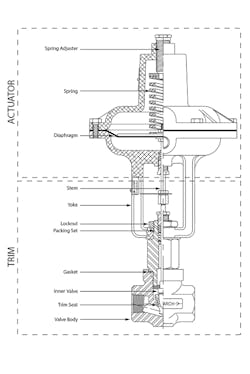
Figure 1. The internal elements of a control valve (known as its "trim") are key factors in the valve selection process.
Choosing the right device
For manufacturers with continuous process operations, proper control valve sizing and the choice of valve body and trim materials are essential steps in optimizing performance and combating erosion-related damage. They could mean the difference between an unplanned shutdown and continued operation.
Other important decisions are involved in identifying the right valve solution. Many leading industrial companies choose globe-style valves for their proven performance and life cycle advantages. Compared to alternative valve designs, this type of device offers:
- High differential pressure across the valve
- Better control performance
- Better low flow (partial load) performance
- Use for steam, water or water/glycol media
- Smaller physical profile than a comparable
ball valve
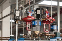
Image 3. A globe-style control valve
Depending on the type of supply, the globe valve’s disc is moved by a hydraulic, pneumatic, electrical or mechanical actuator. The valve modulates flow through movement of a valve plug in relation to the port(s) located within the valve body. The valve plug is attached to a valve stem, which is connected to the actuator.
Some globe valve designs feature a bolted bonnet and post-guided inner valve. They are well-suited for modulating control of liquids and vapors in environments where compact size, coupled with the ability to withstand high temperature and pressure, are essential (See Image 3).
Globe valves meet demanding process application requirements because of the quality and precision tuning of their trim components. For example, valves are available with pre-formed diaphragm and multisprings to ensure extremely linear travel versus input signal performance. Plus, valves utilizing a single O-ring and Nylatron guide bushing provide minimum hysteresis. Technicians can adjust the spring preload to suit specific closing force requirements and make use of adjustable travel stops.
A significant improvement in control valve technology is the implementation of 316 stainless steel for trim material such as the valve body, bonnet and inner valve. This ensures longer trim life, and as such, less downtime and lower device repair and replacement costs. The most common stainless steel on the market, 316 is an austenitic grade with the addition of 2 to 3 percent molybdenum, which further improves corrosion resistance. It is often referred to as a marine-grade stainless steel because of its effective resistance to chloride corrosion in comparison to other stainless steel grades. The material also has superior welding and forming qualities.
Many users choose to mate globe valves to high-accuracy, electropneumatic I/P positioners to position the device based on a 4-20 mA control signal. The latest generation of I/P positioners delivers fully automatic determination of the control parameters and adaptation to the final control element.
Benefits to plant operators
A demanding business environment calls for the most reliable and accurate control of production processes possible. Failure to meet specific operating standards can have serious consequences for quality and safety, while running an inefficient operation can significantly affect the financial margins for the product. In both cases, optimal control valve performance is vital.
Industrial organizations will benefit from working closely with their manufacturer representative or instrumentation supplier to specify an appropriate measurement and control solution. This collaboration can meet important performance criteria such as:
- Precise flow and pressure control resulting in stable and consistent production results
- Lower repair and maintenance costs resulting from longer valve trim life
- Fewer unplanned shutdowns and increased plant availability
- Efficient energy usage and reduced costs
Control valves must withstand the erosive effects of the flowing fluid while holding an accurate position to maintain the process variable. A valve will perform these tasks satisfactorily if it is sized correctly for the application, and designed and built in a way that is appropriate for the process service conditions.
Conclusion
There is no doubt that enhanced control valve technology helps all kinds of manufacturers continually improve process efficiency and product quality, while safeguarding people, plant assets and the environment. The right solution can support a comprehensive system to track every step of the manufacturing process.
Key to the outcome of any control valve project is the assistance of qualified engineers, who analyze the application to ensure the right instruments are selected and sized correctly. Valve manufacturers that understand control performance can share those capabilities and show they can conform to a user’s performance specifications.
Brian Kettner is marketing manager for Badger Meter. He has more than 14 years of experience in fluid system technology, combining marketing, sales and product development roles, with a focus on the processing industry. Currently, Kettner manages Research Control Valve and Preso differential pressure product lines for Badger Meter.