Coupling electromagnetic simulation with frequency-agile microwave power for precision drying of advanced materials
Key Highlights
- Electromagnetic simulation identifies field behavior before fabrication, reducing design risk and prototyping costs.
- Coupled electromagnetic and thermal modeling improves temperature uniformity and process predictability.
- Frequency-agile microwave systems adapt to changing material properties for better power absorption.
- Simulation, controls, and validation create a reliable pathway from laboratory testing to industrial scale-up.

Industrial microwave drying has entered a new phase of engineering innovation. Performance expectations continue to rise for manufacturers processing advanced powders, specialty chemicals, ceramics, battery materials, and other high-value products. Uniform heating, stable power transfer, and predictable scale-up are now baseline requirements.
Meeting these requirements demands control over the electromagnetic environment. Advanced simulation tools, combined with frequency-agile microwave power systems, are enabling a more data-driven and outcome-predictive approach to microwave drying system design.
Building accurate digital models for microwave system design
The foundation of advanced microwave process design begins with full-wave electromagnetic simulation to accurately model how the microwaves behave, propagate, and interact with objects. Simulation is critical for high-power microwave (HPM) engineering because, in HPM systems, where power levels are high, even minor design inaccuracies can lead to catastrophic failure, making simulation essential for visualizing field distributions, identifying hot spots, and ensuring reliable operation without expensive physical prototyping. Modeling software such as COMSOL Multiphysics solves for Maxwell’s equations across a discretized mesh of the microwave applicator, cavity, and load.
Engineers can define boundary conditions, assign electrical and thermal material properties, and calculate field behavior throughout the geometry of the cavity.
This approach provides insight into:
- Electric field intensity distribution
- Node and anti-node formation
- Return loss and reflected power
- Power density within material domains
- Leakage risk at seals or openings
- How to maximize peak power absorbency into the material
Return loss calculations quantify how much applied power is reflected back to the source. In well-optimized systems, simulations may show return loss values below −10 dB, indicating that the majority of applied power is absorbed by the load.
Frequency-dependent absorption can also be evaluated to identify the optimal operating frequency. When the process is coupled with a frequency-agile microwave system, simulation can be greatly valuable in understanding how a material’s best absorption frequency may change during the process and/or with variables to the load.
Preparing computer-aided design models for reliable simulation
Computer-aided design (CAD) models must be simplified. The first step involves creating a virtual model of physical components to be tested. This model needs to accurately capture the geometry, materials, and relevant features of the cavity, or vessel, under study. Cavity dimensions are evaluated relative to wavelength to determine an appropriate center frequency, such as 915 MHz for larger industrial cavities.
The accuracy of the virtual prototype directly affects the reliability of the simulation results; therefore, all critical dimensions, interfaces, and material properties should be carefully defined.
In the second step, an appropriate numerical solver must be selected to simulate the problem. The selection depends on factors such as geometry complexity, frequency range, material properties, and type of analysis (scattering, radiation, or coupling).
In the third step, simulation parameters such as boundary conditions, frequency range of the computation, and required output parameters are defined.
In the final step, post processing is performed for the results to examine the behavior of the computational domain.
This disciplined approach ensures that simulation results reflect the actual boundaries the microwaves will encounter.
Coupling electromagnetic and thermal simulations for better process control
Electromagnetic results provide absorbed power density. That absorbed power becomes the heat source in a coupled mechanical and thermal simulation.
Temperature rise and thermal distribution is then simulated based on material thermal properties, heat transfer mechanisms, and process assumptions.
There is a direct relationship between electric field strength, microwave power density, and temperature increase.
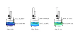
For example, in bulk powders, the distribution of absorbed energy may differ from that in a solid block. Mixing behavior, airflow, and insulation conditions all influence the final uniformity of temperature (See Figure 1).
By coupling electromagnetic and thermal simulations, engineers can estimate:
- Power required to reach target temperature
- Time to cure or dry
- Location of potential hot & cool spots
- Likelihood of arc events
- Ideal processing frequency based on the material dielectric properties
These simulations replace the outdated, and costly, trial-and-error prototyping that has previously been the norm in designing microwave processing systems.
Modifications to feed location, applicator design, cavity geometry, or waveguide configuration can be evaluated quickly in software before fabrication.
Managing microwave field behavior in complex cavities
Field patterns differ significantly based on the cavity itself, the dielectric properties of the material, and the load volume within the cavity. Single-mode cavities exhibit clear, equally spaced nodes and anti-nodes at specific frequencies.
Multimode cavities produce more complex and shifting field distributions, especially as cavity size increases relative to wavelength.
In industrial-scale equipment, multimode behavior is common. As material properties shift during drying, node locations can move. These shifts affect uniformity and reflected power levels.
For a given frequency, there is a certain cavity size with dimensions X * Y * Z that is resonant, meaning it will produce a single-mode field pattern inside the cavity therefore creating hot and cool spots. In frequency-agile systems, deviating from that exact frequency (of resonance), the pattern will deteriorate, mitigating the hot and cool nodes and resulting in more of the power being evenly absorbed by the load.
Systems capable of adjusting operating frequency provide additional flexibility in maintaining stable microwave power transfer into the material. Frequency tuning allows engineers to operate within bands identified during simulation as providing strong absorption and favorable field distribution.
Simulation allows engineers to design optimized systems for complex cavities.
Integrating simulation with mechanical design and controls
While simulation is incredibly effective, giving engineers greater insight to the process, simulation alone does not deliver a production-ready system. The engineering workflow moves from electromagnetic modeling to thermal validation, mechanical design, fabrication, and testing.
Mechanical layout must support proper waveguide routing, feed location, and cavity sealing.
High-power waveguides, transitions, horns, pressure windows and other components are selected based on power level, frequency band, processing environment, and application.
In some cases, a custom applicator design or other components may be required.
Controls integration is equally important. Process stability depends on accurate instrumentation and system monitoring. Industrial microwave systems typically incorporate:
- Temperature sensors
- Forward and reflected power monitoring
- Arc detection sensors
- Microwave leakage alarms
- PLC-based integration and safety circuits
Real-time power measurement and fault handling improve reliability and operator confidence. Safety systems are integrated to mitigate potential arc risks identified during simulation. Monitoring devices provide feedback that aligns physical operation with modeled expectations.
This structured progression from model to validation reduces uncertainty during commissioning and supports predictable scaleup.
Industrial microwave drying applications across advanced materials
Electromagnetic simulation is relevant across a broad range of industries such as heating and drying of advanced materials, advanced powders, chemicals, biomass, ore processing, high value products drying, and other applications that require precision and control over the applied energy to heat and/or chemically transform the material load.
These applications demonstrate the diversity of materials and process conditions encountered in industrial microwave systems.
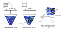
In one example case study, simulation evaluated feasibility, power requirement, feed placement, cavity type, and arc risk before hardware construction (see Figure 2).

Dielectric property measurements across temperature and frequency were incorporated into the model to improve accuracy (see Figure 3).
Understanding complex permittivity over the process temperature range is essential. Accurate dielectric data improves prediction of power absorption and field distribution.
A structured engineering approach to microwave drying system design
A disciplined microwave system design process can be summarized in four coordinated phases:
- Model. Develop a simplified and accurate CAD representation. Assign material properties. Solve Maxwell’s equations to evaluate field distribution and return loss.
- Couple. Use absorbed power density as input to thermal simulation. Estimate temperature rise and identify hot spot regions.
- Integrate. Translate simulation results into mechanical layout, waveguide configuration, and control system architecture.
- Validate. Fabricate pilot systems. Measure reflected power, temperature distribution, process stability, and defined process output. Refine models as needed or move to scale.
This structured method supports predictable performance and reduces development time. It allows engineers to move forward with quantitative insight rather than empirical adjustment alone.
Simulation and frequency-agile technology improve industrial microwave drying
Industrial microwave drying continues to gain relevance as manufacturers pursue higher-value materials and more efficient processes. Control over electromagnetic field distribution, impedance stability, and thermal response has become central to process success.
By combining full-wave electromagnetic simulation with frequency-agile RF power systems and integrated controls, engineers gain the ability to design, validate, and scale microwave drying systems with greater confidence. The result is improved uniformity, efficient energy transfer, and a disciplined pathway from laboratory validation to industrial deployment.
About the Author

Lori Tybon
Lori Tybon leads marketing & business development efforts at Crescend Technologies (Glendale Heights, IL), focusing on advancing solid-state microwave energy for applications in heating, drying, and advanced industrial processes.