Dust collection system fan performance and selection criteria
Key Highlights
- Proper fan sizing based on air volume (cfm) and static pressure is essential for effective dust collection performance.
- Ducting layout, including straight runs and elbow placement, significantly impacts fan efficiency and system airflow.
- Elevation changes affect air density, requiring correction factors to ensure consistent system performance at different altitudes.
- Using multiple fans in parallel increases airflow, while series configurations are suited for overcoming higher static pressure demands.
- Designing the system around the fan's capabilities ensures optimal operation, energy efficiency, and longer equipment lifespan.

Dust collection systems are commonly regarded as a necessary but non-revenue-generating component of industrial operations. While essential for maintaining air quality and regulatory compliance, they are often undervalued from a return-on-investment perspective. Consequently, many systems suffer from inadequate design, insufficient maintenance, and ad hoc modifications lacking proper engineering analysis — all of which can lead to suboptimal performance.
Two primary components fundamentally influence the performance of a dust collection system: the hood and the fan. In a previous article, I provided an in-depth examination of hood design parameters and their impact on capture efficiency. In this article, I will explore the role of the fan in system performance and discuss selection criteria and common design pitfalls.
Sizing a dust collection system fan
Industrial fans such as the ones typically used in dust collection systems are heavy-duty, durable fans designed to move large volumes of air continuously, often in harsh environments, for extended periods of time and with multiple starts and stops. These fans are built with robust, high-grade materials and components to withstand high temperatures, dust, humidity, and other demanding conditions.
The fan is the primary driver of any dust collection system. If the fan is not sized correctly, then the whole system will fail to adequately collect dust. The two main sizing factors for fans are air volume, commonly expressed in cubic feet per minute (cfm), and static pressure, commonly expressed in inches of water gauge (“WG).
The air volume (cfm) requirement is derived from the hood design, which is dependent on several factors, including distance from the dust source, how much containment exists, size, and/or manufacturer’s requirements. More detailed information on hood design can be found in the ACGIH Industrial Ventilation: A Manual of Recommended Practice.
The static pressure (“WG) required comes from the system design. Static pressure calculations must be completed either manually or with software. The calculations must take into consideration the air velocity and the length and cross-sectional area of the ducting, as well as all accessories (hoods, inlet isolation valves, stacks, dirty dust collector filters, etc.).
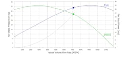
From these two parameters, the manufacturer will supply a fan curve (Figure 1). The fan curve will dictate the horsepower required to run the fan with the outlined parameters. One item that is often overlooked when sizing a fan is the operating range of the dust collector. When the system is started up with new filter media, the static pressure across the filter media should be below 1 ”WG. However, as the filter media ages and gets dirty, the pressure differential across the media will increase.
End users should be consulted regarding their expectations of this operating parameter. On past projects, I have seen pressure differentials as high as 15 ”WG. If not taken into account, this can cause the entire system to deteriorate, plug up and, ultimately, not function.
Other design parameters that can affect the static pressure and flow requirements include the inlet and outlet ducting arrangement and elevation.
How ducting affects a dust collection system fan
Both the inlet and outlet ducting affect the fan’s efficiency and must be considered when laying out the ducting for the fan. For optimal performance, the ducting connected to the fan inlet should have a straight section with a minimum length of 3 to 5 times the duct diameter. Elbows and offsets too close to the fan can negatively impact the fan’s operating efficiency.
When air travels through an elbow, the air hugs the outside of the ducting. If an elbow is connected directly to the fan inlet, then the air will load the bottom section of the fan impeller. This can overload some of the fan vanes while leaving other cavities empty and can reduce the fan’s capacity up to 30%.
If this capacity loss is taken into consideration and the fan upsized to account for it, then it is not an issue. However, if the decreased capacity is not considered, it can reduce the airflow and ultimately cause the entire system to operate less effectively than expected.
Over time, uneven air pressure on the fan impeller can cause excessive vibration and, ultimately, premature failure of the fan. If a straight run of ducting cannot be installed for whatever reason, then an inlet box should be considered.
The ducting on the outlet side of the fan must also be considered. Understanding how the outlet ducting affects the fan requires an examination of the fan’s inner workings. The interior of a fan follows a scroll design, causing the air to spiral as it exits the fan. However, for efficient airflow through the duct system, this spiral discharge must transition into a laminar (smooth and uniform) flow, aligned parallel to the duct walls.
To achieve laminar flow, a straight section of duct is required after the fan. For air velocities below 2,500 feet per minute (fpm), this straight duct should be at least 2.5 times the duct diameter. For each additional 1,000 fpm above that, add one additional duct diameter to the straight run. Without this straight run of ducting, the fan efficiency could be reduced.
If it is not possible to install a straight run of duct, the elbow should be installed in the direction of the throw (or scroll) of the air from the fan. Placing the elbow in the wrong direction can significantly reduce fan performance, increase energy consumption, and generate more noise.
Other operational factors that can affect fan efficiency are elevation and having multiple fans in one system. While these factors are not as common as the ones already discussed, if not taken into account, they can cause issues including insufficient air volume and/or reduced static pressure performance.
Effects of elevation on dust collection fan performance
Air density is a critical variable when completing static pressure calculations for a dust collection system. Because air is less dense at higher elevations, the higher the elevation, the fewer air particles in a given volume of air. This variability in air density means that the same fan, rotating at the same speed, moving the same volume of air, moves fewer air particles at higher elevations than at lower elevations.
For example, at sea level — say in Halifax, Nova Scotia — air weighs roughly 1.2 kg/m³ (0.0765 lbs/ft³), but in Denver, Colorado, at 1,609 m (5,280 ft) above sea level, air weighs closer to 1.01 kg/m³ (0.0626 lbs/ft³). If a 3,000-cfm fan in Halifax is moving 79 kg (174 lbs) of air per minute, that same fan in Denver will move about 66 kg (145 lbs) of air per minute. Since the air is less dense at elevation, the fan must move a greater volume of air (cfm) to push the same mass of air as it would at sea level. To do that, the fan either needs to run faster (increased rpm) or a larger fan with a higher cfm capacity must be used.
To account for air density, system designers refer to correction factor tables or calculators to determine the correction factor that should be applied. In the example of a Halifax fan versus a Denver fan, a correction factor of 0.85 would apply. This means that the 3,000-cfm Halifax fan would need to be a 3,450-cfm fan to move the same mass of air in Denver.
When choosing a fan and inspecting the ratings, it is crucial to remember that fan curves are published at standard conditions (usually sea level, 20 °C).
How multiple fans in one dust collection system affect performance
Two options are available for adding an additional fan to a system: series and parallel. When fans are installed in parallel, the resulting change is an increase in airflow but no change in static pressure. If the goal of the system is to move large quantities of air, parallel fans can be used to increase volume. Conversely, when the system static pressure parameters exceed the existing capacity and a high static pressure is required to maintain air velocity, fans are placed in series.
With respect to dust collection system configurations, if the goal is to add additional dust collection points to an existing system and increase cfm, fans would be installed in parallel (Figure 2, left). If material needs to travel a long distance and maintain transport velocity, fans would be installed in series, as this would require an increase in static pressure (Figure 2, right).
Ensure optimal performance by letting the fan guide system design
As the heart of any air movement or ventilation system, the fan should guide system design rather than be treated as a secondary component. Selecting the wrong fan type — or failing to account for its performance characteristics — can limit the overall efficiency and effectiveness of the entire system. This often results in inadequate airflow, higher energy consumption, and increased wear on equipment.
When properly matched to the application and selected with a clear understanding of airflow demands, system resistance, and performance curves, fans can deliver optimal performance rather than simply meet minimum requirements. Designing the system around the fan rather than forcing the fan to compensate for system design flaws ensures more reliable operation, better air quality control, and improved energy efficiency. In ventilation systems, “good enough” is rarely good enough.
About the Author

Diane Cave
Regional manager of Eastern Canada at Element6 Solutions
Diane Cave is Eastern lead at Element6 Solutions. She has more than 20 years of experience working with the design, installation and retrofitting of dust collection systems in industries ranging from sawmills and grain installations to food and beverage and specialty chemicals. Her expertise covers all aspects of dust collection systems, from troubleshooting system issues to upgrading systems to meet current codes and standards. Diane has also assessed hundreds of dust collection systems for combustible dust hazards using the latest NFPA codes and standards and conducted her fair share of DHAs. She can also provide advice and design experience for explosion protection systems, vessel retrofits, Pred verification, static bonding/grounding, and vessel strength analysis. Diane has a degree in chemical engineering from Dalhousie University in Halifax, Nova Scotia.


