Protecting pressure instruments from water hammer spikes
Key Highlights
- Water hammer occurs when rapid changes in fluid velocity cause pressure spikes that can damage sensors or shift calibration.
- Common causes include quick-acting valves, pump startups, check valve slam, and trapped air pockets, even in low-pressure systems.
- Sensors should be selected with proof and burst pressures exceeding the maximum expected transient to prevent permanent damage.
- Installing pressure snubbers near sensors helps absorb pressure spikes, protecting the sensing element without compromising response time.
- Proper system design, including valve operation and sensor over-ranging, can significantly extend sensor lifespan and ensure measurement accuracy.
Pressure sensors, switches and transmitters are precision instruments built to hold calibration for years. So, when a unit comes back from the field with questionable readings or no signal, the calibration team’s first instinct may be to suspect the device itself. However, the problem’s actual root cause may have nothing to do with the instrument at all because it could have originated with physical equipment and process conditions.
A likely culprit is water hammer, a pressure spike caused by a sudden change in fluid velocity. It appears in high-pressure hydraulic systems, but also in low-pressure water lines and gear pump systems. The spike may last only milliseconds, too fast for a data logger to capture and even too quiet to hear over plant noise, yet it can permanently shift calibration or destroy the sensing element.
Understanding water hammer
Water hammer, also called hydraulic shock or fluid hammer, occurs when a moving column of liquid is forced to stop or change direction suddenly. Because liquids are essentially incompressible, the fluid’s kinetic energy converts almost instantly into a pressure spike traveling at roughly the speed of sound in the fluid (roughly 4,500ft/sec). This often creates audible banging or knocking, but even quiet systems can experience damaging spikes.
Common causes include:
- Solenoid valves closing rapidly: A standard solenoid valve closes in under 50 milliseconds, making it one of the most common causes of water hammer in process and automation systems.
- Manual valves closed too quickly: Quarter-turn ball valves closed by hand in under a second can generate equally damaging spikes.
- Pump starts and stops: Positive displacement pumps (gear, piston) started across-the-line (also known as direct-on-line), without a variable frequency drive (VFD) or soft starter jump from zero to full flow almost instantly.
- Check valve slam: Swing-style check valves close abruptly upon reverse flow.
- Pump power loss: A sudden trip creates a positive surge on the suction side of the pump and a vacuum condition on the discharge.
- Trapped air pockets: Compressed air releasing rapidly causes localized pressure events.
Damage can occur on both sides of a valve closure or pump shutdown due to water hammer. The upstream side sees a positive pressure spike, while the downstream side can experience a vacuum or sub-atmospheric condition.
The scale and prevalence of water hammer surprises many engineers and technicians because damaging spikes are not limited to high-pressure hydraulics. Even a modest 0.5-inch water line operating at 50 psi and 15 GPM can momentarily see a spike approaching 500 psi when a solenoid valve slams shut, roughly ten times normal operating pressure.
A gear pump started across-the-line can produce a similar result because its internal relief valve is designed to protect against steady-state overpressure, not to catch a transient that forms and dissipates in a few milliseconds, far faster than a mechanical relief device can respond. Spikes of two to five times normal working pressure are common in these situations, meaning a system that normally runs at 60 psi can see transients above the proof pressure rating of many sensors.
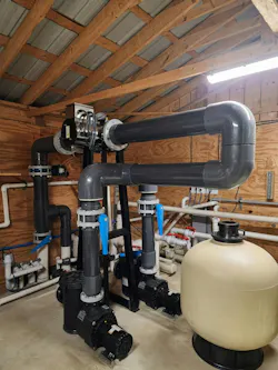
Water hammer is a broad industrial problem, and any system experiencing the aforementioned conditions is potentially susceptible, regardless of nominal operating pressure (Figure 1).
Pressure sensor vulnerabilities
A pressure sensor is an electromechanical device in which a sensing element, typically a thin diaphragm, deflects in proportion to applied pressure and converts that action into a discrete or analog electrical signal. An analog signal is produced by a piezoresistive, capacitive or other element bonded to the diaphragm, which is then conditioned by internal electronics and transmitted as an output. Discrete signals may be electronic or electromechanical. Classic hardwired analog output signals include 4-20mA and 0-10V, while HART, IO-Link and other digital fieldbus signals are now common.
Instrument accuracy depends on the diaphragm staying within its elastic limit, meaning it returns to its original shape once pressure is removed. Sensor datasheets typically define the normal operating pressure range and the instrument vulnerabilities when exposed to higher-than-normal pressures:
- Measuring range (or Max working pressure): The normal working range of pressures the instrument can measure. It may also be expressed as a lower range limit (LRL) and upper range limit (URL). The instrument may be calibrated for the full range or a smaller portion of it, but calibration does not change the ratings.
- Proof pressure (or Permissible overload pressure): The maximum momentary pressure a sensor can withstand without a permanent shift in calibrated output. It may also be called maximum working pressure (MWP) and may be expressed as a pressure or as a multiple of full-scale (FS) range, such as 2× or 3× FS.
- Burst pressure: The pressure that causes catastrophic mechanical failure, such as diaphragm rupture, port breach or potential process fluid release. It may also be called the overpressure limit (OPL) or sensor overload limit, and it may be expressed as a pressure or as a multiple of full-scale, typically 5× FS or higher.
A spike that exceeds proof pressure, even once and briefly, can result in a permanent zero or span shift. This explains the most common water-hammer-related failure symptom, along with those listed below.
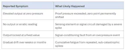
If a replacement sensor fails the same way as the first, the sensor was likely never the problem, but instead the system.
Protecting sensors
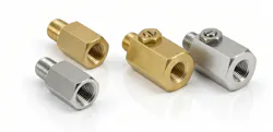
A pressure snubber, also called a pressure arresting device, is a small, low-cost fitting installed between the process connection and the sensor. It restricts how quickly a pressure change reaches the sensing element, absorbing the spike while still allowing the sensor to track normal process pressure over time.
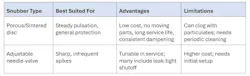
Snubbers must be compatible with the process fluid, pressure and connection size, typically 0.25” NPT (Figure 2). They should be installed as close as possible to the instrument. After installation, the sensor response should be verified to ensure the snubber is not too restrictive as this would slow response time to an unacceptable level.
Selecting sensors for high-spike environments
Where the risk of water hammer is anticipated, sensor selection deserves careful attention. A sensor’s proof pressure should exceed the highest anticipated spike, with margin. For example, a 100 psi sensor with a 2× proof rating withstands only a 200 psi transient, which may not be enough. Sensors with ceramic diaphragms typically have a higher proof pressure rating, making them a good choice for applications prone to pressure spikes. In process applications where sensor failure could release hazardous media, burst pressure must also be evaluated against the maximum possible pressure (Figure 3).
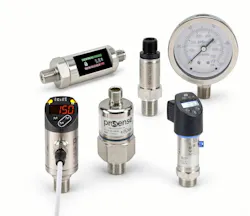
One tempting fix is to over-range the sensor, such as specifying a 0–500 psi unit on a system that normally runs at 50 psi to gain headroom for accommodating spikes, but that approach sacrifices resolution and accuracy at normal operating pressure. In most cases, a correctly ranged sensor paired with a snubber is the better solution, preserving measurement accuracy, while protecting the sensing element from transients.
Stopping spikes before they stop sensors
Water hammer is a common, and commonly overlooked, cause of premature pressure sensor failure, and it is not limited to high-pressure applications. Any process experiencing the aforementioned conditions with a fast-acting valve, a DOL pump or a check valve can generate a spike many times normal operating pressure. These events can occur and dissipate too quickly to be logged and may never be heard, leaving only a failed sensor as evidence. Careful process design can reduce water hammer, and a correctly selected sensor paired with a snubber will provide long service life and reliable performance.
About the Author
 Bryce Ligon
Product engineer at AutomationDirect
Bryce Ligon is a product engineer who supports process measurement products at AutomationDirect. He has over a decade of experience designing and commissioning automated fueling systems in the data center industry. He holds a BSME degree from Georgia Tech.