An in-depth guide to industrial valves and their roles in fluid systems
Key Highlights
- Valves are classified based on their primary functions: on/off, flow control, directional flow, overpressure protection, and excess flow control, each with distinct symbols in piping diagrams.
- Choosing the right valve involves understanding its specific capabilities, such as quick shutoff, precise flow regulation, or backflow prevention, tailored to system requirements.
- Flow management is critical; the flow coefficient (Cv) helps determine a valve's capacity, but selection must consider system pressure, temperature, media, and desired flow rate.
- Overpressure protection devices like relief valves and rupture discs prevent system damage by releasing excess pressure automatically or gradually.
- Proper valve selection enhances system safety, uptime, and efficiency, making knowledge of valve functions and classifications vital for engineers and operators.
Throughout industrial plants worldwide, small-bore fluid systems are crucial to safe and productive operation. And within those systems are countless valves providing critical flow control for power generation, oil and gas refining, chemical processing and much more.
To properly select valves for each application, fluid system designers and operators need to understand not just what types of valves are available, but how their functions differ and what specific capabilities they provide. Some valves are engineered for starting and stopping fluid flow, while others control flow direction, regulate flow level or protect a system from overpressure. Finding the right valve for your application means knowing how you need the valve to perform in your application.
Valve classification and recognition
An industrial fluid system valve performs one of five main functions: on/off, flow control, directional flow, overpressure protection and excess flow control. Each of these functions has an industry-standard symbol used in piping and instrumentation diagrams (P&IDs) to clarify a valve's purpose within a system. Let's look at each type.
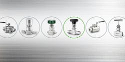
1. On/off — Perhaps the most basic fluid control building block, the on/off valve is recognized in P&IDs by its bowtie shape. An on/off valve starts and stops the flow of fluid. It is that simple, and yet you will find yourself presented with several options when selecting one. Four common examples include:
- Ball valves that use a handle to rotate a ball within the valve that blocks or permits fluid flow through the valve.
- Plug valves that have a similar appearance and construction, but the handle spins a plug (usually cylindrical) inside the valve instead of a ball.
- Bellows valves that have a taller, cylindrical stem and use an expanding and contracting bellows to restrict fluid flow to precise levels. When the handle is spun, an actuator is pressed onto the bellows.
- Diaphragm valves that are similar to bellows valves, but use an actuator pressing on a flexible diaphragm to restrict or allow flow when the handle is spun.
In many processes, it is necessary to cut off fluid flow quickly in emergency situations. Fluid systems often operate at high pressures and temperatures, and some fluids are innately hazardous, so on/off valves play a key role in maintaining system safety and avoiding risk to operators.
2. Flow control — This valve type is used to adjust fluid flow through a system, from basic regulation to fine metering. Its P&ID symbol looks like the one used for an on/off valve, but it includes an extra downward-pointing triangle at the center of the “bowtie” to indicate the flow control functionality. Controlling or throttling flow is commonly achieved using a needle valve. In these valves, a needle at the end of an actuator within the valve stem blocks flow through the valve as it is lowered by turning the handle.
Needle valves are like bellows and diaphragm valves in that they can provide on/off functionality if necessary, but they are primarily designed to control flow rates. Stem position, stem type and orifice size all determine the flow rate possibilities.
3. Directional flow — When you see a P&ID icon that shows a downward sloping arrow between two vertical lines, it indicates a directional flow valve. This valve type keeps fluid flowing in the right direction and can also be used to alter the direction of flow within a system.
Common valves used for directional control include check valves, which prevent backflow and keep fluid moving in one direction, and multi-port ball valves, which can provide the on-off functionality of ball valves while allowing the operator to re-direct fluid flow based on the direction in which a handle is turned. It is important to note that while directional valves can provide on/off functionality, they do not throttle flow.
Going with the flow
Flow is the continuous, steady movement of liquids or gases that a given system needs for ideal operating conditions, and valves are the components designed to control flow by stopping, throttling or redirecting it.
As a liquid or gas flows, it moves from conditions of higher pressure to those of lower pressure, and this flow is typically recorded as a ratio of distance or volume per unit of time. Flowmeters measuring this may deliver data in meters per second, gallons per day or liters per minute, for example.
A valve permits flow based on several factors, including things such as the flow path through the valve and the diameter of the valve’s end connection. Manufacturers typically provide a flow coefficient, or Cv, to help users better understand a valve's ability to control flow. The higher a valve's Cv, the higher its flow rate.
Just because a valve has higher flow rate does not automatically make it the best choice: Some valves are engineered with a flow coefficient of near zero, depending on a system's characteristics and operating requirements. You will need to determine the proper Cv for your system based on pressures, flow rates, temperatures and media.
4. Overpressure protection — Relief devices are vital in any system that operates under pressure. By preventing pressure buildup beyond a prescribed limit, relief valves and rupture discs are the last line of defense against overpressure conditions and a potential blowout.
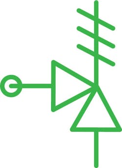
You can calibrate relief valves to open gradually as pressure increases, or to open automatically when a predetermined pressure level is reached. Additionally, you can use bleed valves and purge valves to vent or drain fluid for maintenance or other situations. Do not underestimate the importance of overpressure protection. It is a way to safeguard your plant while keeping things running if over-pressurization occurs. Overpressure protection valve symbols look like two triangles sharing a common point with an antenna-like structure above them.
5. Excess flow control — System safety is also a function of excess flow valves, which help contain uncontrolled fluid releases. These activate when the flow through a valve reaches a predetermined value. This excess flow condition will trip a poppet within the valve, quickly stopping most of the uncontrolled release of the system media. When the pressure equalizes, the excess flow valve will reset itself.
These valves are indicated in P&IDs by a rectangle with constrictions on one end and a circle in the middle. The relatively simple functionality of an excess flow valve cuts down on the need for complex bypass mechanisms while also reducing maintenance time.
The better you understand fluid flow and how to manage it with different types of valves, the more prepared you are for selecting the components best suited for your fluid system design. Ultimately, this enables you to engineer, operate and maintain a more reliable system that delivers safety, uptime and efficiency — and the right valves make it happen.
About the Author
Matt Dixon
Global Technical Lead for Swagelok Company
Matt Dixon, Global Technical Lead for Swagelok Company, began his career with the company in 1998 as an engineering co-op student and has worked as an assembly, welding, and manufacturing engineer in an array of capacities since, supporting the production of various product lines and the designing and building of assembly and test equipment. He has extensive experience in developing, testing, and troubleshooting sampling systems.


