Effective dust explosion isolation is as important as explosion protection

Combustible dust explosion protection for any device or system, such as dust collection, centralized vacuum cleaning, pneumatic conveying, drying, milling (i.e. size reduction), receiving vessels (i.e., silos, bins, etc.) is a well-known and highly discussed topic. Explosion isolation, on the other hand, is less often considered and emphasized, though it is absolutely as important as explosion protection. When explosion protection is properly provided, explosion isolation becomes exponentially even more important.
Explosion isolation should be provided for any device or system where the possibility an explosion can occur and where the explosion pressure or flame-front can subsequently propagate. Typical examples are dust collection, centralized vacuum and pneumatic conveying systems, mechanical conveying systems (e.g., bucket elevators), dryers, and milling equipment, among others.
It is not possible in a single article to provide a thorough discussion of this topic for all the typical explosion hazards; therefore, this article will only discuss dust collection systems, which are the most prominent combustible dust hazard (and also combustible dust mitigating factor) and offer a comprehensive review of the need for explosion isolation (when an explosion hazard exists).
What happens when an explosion occurs in a dust collector
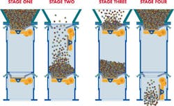
When an explosion occurs in a dust collector without explosion protection, the following is a general description of what happens:
- Immediately (faster than we can observe, typically in microseconds) the pressure inside the dust collector rises to the Pmax value. Typically, this is in the range of 80 to 120 psig.
- This “pressure wave” creates extensive damage to the dust collector, resulting in a “shrapnel” effect.
- Within milliseconds, the “fire ball” (i.e., heat and flame front) occurs.
- Due to the destruction caused by the pressure wave, the fire ball escapes, and secondary effects can occur with excess combustible dusts from the dust collector.
When an explosion occurs in a dust collector with explosion protection, whether explosion venting or chemical suppression, the following is a general description of what happens:
- Immediately (in microseconds), the pressure rises either to a point where the explosion vent bursts or where the pressure-rise device detects an explosion and initiates the chemical suppression.
- With chemical suppression, the fire ball is suppressed and extinguished.
- With explosion vents, the explosion is released (or vented) to the outside before it can destroy the dust collector, etc.
- It is important to note that neither method of explosion protection eliminates the pressure wave or the fire ball generated. This is obvious for the vented explosion but not for the chemically suppressed explosion, which in a very general sense, stops the fire ball from “maturing” into the full event but does not totally eliminate the pressure, heat and burning embers within the dust collector.
Why go through this explanation? The discussion is critical to understanding the important fact that sufficient pressure is available to propagate the event from the dust collector through the connected ducting. Plus, there is sufficient heat and flame or embers to either ignite dust within the ducting or create a “blowtorch” effect (pressure and flame) at the dust collection hoods. The preceding simplified explanation allows for a more thorough examination of why explosion isolation is absolutely necessary.
How a dust explosion propagates through a dust collection system
In the context of a dust collector explosion event, propagation refers to the spreading of airflow through the connected duct system. A typical dust collection system requires 0.51 to 0.87 psig (14 to 24 inches water gauge) vacuum to induce the necessary airflow for proper dust collection (assuming a proper system design, which is frequently not the case). During a vented explosion, the pressure generated is the P-reduced value. For most dust collectors (assuming adequate physical condition), the P-reduced pressure is in the range of 3.5 to 4.5 psig (about 97 to 124.6 inches water gauge). This is true despite the “release” of the vent at about 1.5 psig. For a chemically suppressed explosion, the P-reduced range would be similar (though it can be higher for cylindrical vessels such as cyclones, etc.).
This P-reduced pressure significantly exceeds the pressure induced by the dust collection system’s fan package. (NOTE, the fan should be shut down immediately upon detection of an explosion event.) Typically, dust collection duct diameters can range from large (exceeding 24 inches) to small (3 inches). The positive pressures generated by a vented or chemically suppressed explosion can easily create significant air, gas and combustible dust flow, in reverse, through the entire system, resulting in emissions of some form from the hoods or duct connections where dust collection normally occurs. Considering these dust source locations are usually in proximity to personnel, this is highly unacceptable.
An internet search yielded article after article confirming that sufficient pressure would be generated to both overcome and “push” air, gas, flame/embers and combustible dusts backwards through the entire dust collection system, discharging flames and/or embers into the areas where the hoods are located. This can easily result in secondary explosions or flash fires, potentially creating additional injuries and property damage.
The preceding assumes that there are no accumulations of material within the ducts, which, based on my experience with more than 2,000 dust collection systems, is a very unlikely scenario.
The “backwards” flow from the explosion is at a higher initial, positive pressure than the original airflow of the dust collection system. This results in higher duct velocities and, more importantly, higher turbulence within the ducting system. This combination “lifts” or re-aerates the dust in the bottom and on the interior walls of the ducting, providing additional fuel for the flame front and unspent fuel as it exits the hoods or duct connections. The result can be pressure piling and/or additional combustible dust available for secondary explosions and/or flash fires.
Without proper isolation, if the dust collector is connected to a vessel such as a cyclone, bin, silo, mixer, etc., the increased pressure of the pressure piling can result in a much more destructive explosion that could overwhelm any explosion protection on that vessel. This can be disastrous and could result in even more secondary explosions.
Dust collector explosion isolation devices
Explosion isolation involves isolating the ducting connected to the dust collector as well as the collected material discharge and the clean-air discharge (e.g., ducting to the fan package, etc.).
Isolating ducting into the dust collector
Methods of effective isolation for the duct or ducts into a dust collector can be passive or active. Passive devices do not require external activation, while active devices require activation by an external source.
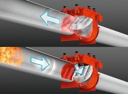
Passive isolation. The major passive isolation device used is a back-draft damper (Figure 1). A back-draft damper is essentially a check-valve that inherently closes when the airflow reverses in the duct. If an explosion occurs in the dust collector, the resulting pressure and airflow from the collector automatically closes the damper, preventing the fireball from propagating through the duct (Figure 2). The damper must be located a specified distance from the dust collector to allow enough time for it to close. If the device is too close to the explosion source, as shown in Figure 3, it will not close quickly enough to prevent propagation.

The positive features of back-draft dampers are their simplicity, proven performance, and passive operation. Negative factors are the significant differential pressure across the damper (2 to 4 inches water gauge is typical), possible wear and/or accumulations on the flapper, and a limitation on the dust’s Kst value (usually under 300).
Active isolation. The range of active isolation devices used is significant and includes chemical isolation (Figure 4), pinch valves, and fast-acting slide gates, among others. All active isolation methods require a device to detect the rapidly rising pressure from an explosion and “signal” the isolation device to activate.
The major advantages of these devices are their ability to isolate in either direction and their ability to be used to isolate on the clean-air discharge of the dust collection system. The major negative factors of active isolation are usually cost and the need to periodically certify the devices’ effectiveness, which can involve costly maintenance contracts.
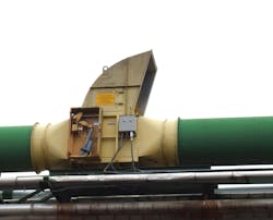
While some facilities have tried to use abort gates (Figure 5) as explosion isolation devices, these devices do not operate quickly enough to provide effective explosion isolation. An abort gate should only be used for fire or similar protection, where the gate’s activation speed is sufficient.
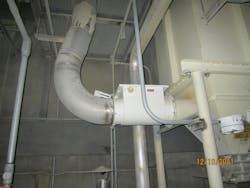
Additionally, it is important to design the dust collection system in a way that allows the use of effective isolation devices. For example, on the dust collection system shown in Figure 6, it would be difficult to provide effective explosion propagation isolation with so many branches of ductwork converging so close to the dust collector.

Isolating the collected material discharge
The collected material discharge is an often-ignored source of possible destructive propagation of an explosion event, but it is as important for isolation as the ducting into the dust collector. During an explosion, it is highly likely that embers and/or flames will be directed toward the collected material discharge. Whatever device is used to isolate these negative effects is critical to effectively isolating the collector from the rest of the system.
Simple slide gates or butterfly valves are not isolation devices because they must be opened to allow material discharge from the dust collector, and when the valve is open no isolation is provided. Also, the use of “material chokes” (i.e., maintaining a level of material in the hopper) is not allowed for isolation as the material is fuel for an explosion and can result in additional hazards and risk.
The devices that provide true isolation are rotary airlock valves and double-dump valves.
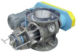
Rotary airlock valves. Rotary airlock valves (Figure 7) are the most common method of isolating a dust collector’s material discharge. The valve consists of a rotor with a shaft and multiple vanes inside a metal housing. As the rotor turns, material from the dust collector fills the pockets between the vanes at the top and then discharges from the pockets at the bottom. The valve maintains isolation because at least two vanes are in contact with the housing at all times. The valve can be used with or without a screw conveyor as the combination of the two is often required for removing collected material from larger dust collectors.
NFPA 69 includes specific requirements that are necessary to qualify as a Class 1 rotary airlock valve, including a rotor clearance of 0.008 inch or less and fixed rotor tips, among other requirements. Rotary valves fabricated with flexible tips are not acceptable.
Double-dump valves. Double-dump valves (Figure 8) consist of two hinged flaps with a chamber in between them. The valves alternate opening and closing so that one flap is closed at all times. This allows material to be discharged while maintaining isolation of the dust collector (Figure 9). Double-dump valves are most commonly used for abrasive materials but also require more headroom than rotary airlock valves.
Isolating the clean-air discharge
Finally, explosion isolation of the clean-air discharge of the dust collector is also a consideration. If the system is located outside and discharges to atmosphere, most facilities will not provide isolation but will design the system to discharge safely into the surroundings. However, if the system is located inside and/or the cleaned air is returned to the inside, then explosion isolation is recommended. The method used is likely to be an active device because a back-draft damper cannot be used.
About the Author

Jack Osborn
Senior Project Engineer
Jack Osborn is senior project engineer at Airdusco EDS and a member of Processing’s editorial advisory board. He has more than 50 years of experience in dust collection systems, centralized vacuum cleaning systems, pneumatic conveying systems, and all types of bulk handling systems. He has either designed or evaluated (e.g., engineering studies/audits, performance testing, etc.) more than 2,000 dust collection systems during his career and is a participating member of all six NFPA combustible dust committees.