Five essential steps to ensure reliable centralized vacuum cleaning performance
Key Highlights
- Understand the specific characteristics of materials being vacuumed, including particle size, shape, and cohesiveness, to inform system design and prevent blockages.
- Strategically locate filter receivers and vacuum sources within a 250-foot radius to maximize coverage and system efficiency.
- Accurately determine the number of operators who will use the system simultaneously to avoid overloading and performance issues.
- Use hoses with a diameter of 1.5 to 2 inches and keep hose lengths under 25 feet to ensure optimal airflow and system performance.
- Calculate maximum system performance by considering airflow, velocity, and operator load to prevent undersizing and ensure compliance with safety standards.
Centralized vacuum cleaning (CVC) systems represent one of the most important methods for providing effective industrial housekeeping and combustible dust compliance and control. Yet these seemingly simple systems are frequently misunderstood and fail to operate reliably due to errors in design, equipment selection, and general use. During my more than 50-year career, I have seen hundreds of these systems sitting idle and unused due to poor performance.
In this article, I will provide five proven steps processors should take to ensure successful CVC system performance and achieve combustible dust compliance.
Step 1: Know your materials’ characteristics
The first step to ensuring CVC system success is to know the pertinent characteristics and quantities of the materials involved. Some materials (such as carbon black, many food products, grains, etc.) are easy to vacuum, while others (such as metal oxides, resins, certain metal dusts, etc.) present major challenges.
Particle size and size distribution are also very important. It is generally more difficult to convey a mix of particle sizes than it is to convey uniformly sized particles. Larger particles, flakes, splinters, etc. can present major problems for CVC systems. For example, paper and films tend to “ball-up” and plug the tubing. Sawdust can consist of multiple shapes, but it only takes one oddly sized chip or splinter to plug and render a branch line inoperative. On the other hand, while grains can range in particle size, they tend to be easier to convey than many other materials.
Additional characteristics such as cohesiveness, adhesiveness, temperature, particle shape, etc. can also be important.
Also, remember that the process material is not all you need to consider. A CVC system may capture anything that will fit into the hose, including liquids, oils, nuts, bolts, plain old dust, etc.
How can you “design” for all these possibilities? The best method is to consider the worst-case scenario and be conservative with performance requirements.
Step 2: Specify where the system will be used
CVC systems are limited in the area they can successfully cover. The actual range depends on many factors, but a rough estimate is within 250 feet of the filter receiver/exhauster package.
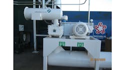
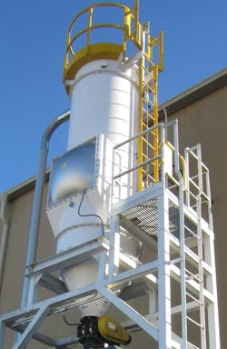
The key is the location of the filter receiver (i.e., dust collector) and the vacuum producer. Where this equipment is installed, whether inside or outside, represents the center of the 200- to 250-foot radius (depending on turns and other factors) that a properly designed system can cover.
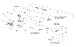
Once you have determined where the main equipment items will be located, create a general plan view (which may require multiple levels for multiple floors) and determine where the hose connections will be (discussed later). Be generous, as the number of hose connections does not adversely effect the performance of the system and these connections are relatively cheap to install.
Step 3: Determine the TRUE number of simultaneous operators
When thinking about how many operators will potentially operate the system simultaneously, be practical and realistic. This is not the time for a “wish-list.” The higher the number of simultaneous operators, the higher the costs and the higher the likelihood of plugging and poor performance.
One operator at time is ideal but often impractical. The next best option is two, which is often viable. Three or more simultaneous operators complicates the system design but is feasible. For the best chance of success, be realistic and minimize the number.
Step 4: Determine the hose diameter and length
The smallest recommended hose inside diameter is 1.5 inch, and the largest recommended inside diameter is 2 inches. Larger hoses are available but are often impractical due to hose weight, equipment costs, availability of tools, etc.
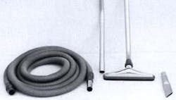
A 1.5-inch hose is best for smaller operators and for cleaning around and inside equipment. A 2-inch hose is best where spills and higher accumulations are common and for locations where quick vacuum cleaning is important.
Hoses used for vacuum cleaning are heavy, with smooth interiors and proper electrostatic grounding. A 2-inch hose is considerably harder to manipulate than a 1.5-inch hose. However, a 2-inch hose can clean an area much more quickly than a 1.5-inch hose.
It is best to design the entire system for a single hose diameter. Mixing diameters creates system design and air distribution problems.
Do NOT exceed 25 feet in hose length, no matter the temptation. Hoses represent the highest energy requirement for the system. Long hose lengths result in poor performance; shorter hose lengths allow for higher airflow, resulting in better performance.
Step 5: Calculate the maximum performance possible for the system
For a CVC system to be successful, it must provide effective performance at the hose connection representing the furthest distance (including turns, etc.) from the filter receiver. This is not as simple as it seems.
Typical problems include:
Insufficient airflow for the vacuum hose. Often, there is stiff competition among vendors for the project. One of the most common methods vendors use to lower their proposal costs is to reduce airflows. This is a subject that warrants a more in-depth discussion, but simply put, a CVC system’s efficiency (ability to vacuum up material) is based on the 3rd power of the velocity of the air into the hose (or tool).
For example, if your 1.5-inch hose is designed for 75 standard cubic feet per minute (scfm), the inlet velocity is about 6,100 feet per minute (fpm), while a 1.5-inch hose designed for 90 scfm has an inlet velocity of approximately 7,300 fpm. You might think the 6,100-fpm (75 scfm) hose would perform about 84% as well as the 7,300-fpm (90 scfm) hose. However, because the efficiency is based on the 3rd power of the ratio, 6,100 divided by 7,300 taken to the 3rd power results in efficiency of only 58%. In the real world, this means that the 75-scfm airflow will take about twice as long to clean up the same area as the 90-scfm airflow. This is a huge difference in actual performance compared to the relatively small difference in airflow.
Designing for multiple operators. Most CVC systems are designed for multiple simultaneous operators. The problem is that most systems are designed only for the maximum simultaneous operators and ignore the fact that the system often only has a single operator.
For example, assume a system is designed for 3 simultaneous operators using a 2-inch hose at 160 scfm each. Also assume the system is designed to operate at 11 inches mercury (hg) vacuum. Since air expands under vacuum, the airflow volume for 3 simultaneous operators will be up to approximately 760 inlet cubic feet per minute (icfm) at the vacuum blower inlet.
In a 4-inch main line to the filter receiver, this would be a velocity of over 8,000 fpm. However, with only two simultaneous operators, this velocity drops to approximately 5,800 fpm. And with a single operator, the actual airflow (limited by the 2-inch hose and initial 2.5-inch tubing) in the 4-inch header (the main piping to the receiver) is only in the range of 3,100 fpm, which will eventually lead to plugging of the 4-inch line. This is a very common problem and is specifically not allowed for combustible dusts, per NFPA combustible dust standards.
Improperly sized filter receivers. Too often, systems are designed for standard conditions (scfm) rather than for actual airflow (acfm) through the filters. This results in under-sizing of the filters, which inherently reduces airflow.
Improper blower selection. Positive displacement (PD) vacuum blowers are often preferred by system designers due to their performance characteristics. However, they are limited to a low number of simultaneous operators. Higher numbers of simultaneous users require centrifugal blower units.
While these are not the only errors I see, they cause the vast majority of problems that hinder CVC system performance.
About the Author

Jack Osborn
Senior Project Engineer
Jack Osborn is senior project engineer at Airdusco EDS and a member of Processing’s editorial advisory board. He has more than 50 years of experience in dust collection systems, centralized vacuum cleaning systems, pneumatic conveying systems, and all types of bulk handling systems. He has either designed or evaluated (e.g., engineering studies/audits, performance testing, etc.) more than 2,000 dust collection systems during his career and is a participating member of all six NFPA combustible dust committees.