Dust collection system design depends on proper transport velocity selection
Key Highlights
- Proper transport velocity prevents dust settling, reducing blockages and safety risks in ductwork.
- Duct sizing must balance air volume and velocity to maintain effective system performance.
- Material properties determine required transport velocity; one standard value does not fit all.
- Maintaining velocity over time requires testing, maintenance, and accounting for system degradation.
Many industrial dust collection systems are installed with limited formal design behind them. This isn’t necessarily due to negligence; it is often a result of time and financial constraints, a limited understanding of the material being conveyed, or reliance on rule-of-thumb approaches. One of the most fundamental and frequently overlooked design considerations is transport velocity.
Why transport velocity is critical in dust collection design
Transport velocity, sometimes called conveying velocity, is defined as the minimum rate of gas movement required to keep solid particles suspended in the airstream, preventing settling and clogging. Simply put, it is how fast the air needs to move to carry dust from the point of collection to the dust collector without allowing the dust to fall out of the airstream and accumulate in the ductwork.
This may seem straightforward, but it is a critical parameter that is often overlooked. If transport velocity is not properly considered, dust will settle out of the airstream and accumulate in the ductwork, leading to reduced performance, blockages, and an increased risk of a deflagration event.
How insufficient velocity leads to hidden dust buildup
The challenge with inadequate transport velocity is that accumulation is not always immediately apparent. Because ductwork is typically opaque, small amounts of particulate can settle unnoticed in areas where air velocity is insufficient to keep dust in suspension — often accumulating to problematic levels before any external signs are visible.
NFPA 91 (2026), Section 9.1, requires that any portion of an exhaust system with the potential for combustible residue buildup and a cross-sectional area greater than 75 in² (approximately 10 inches in diameter) be protected with automatic sprinklers. For larger ducting, this introduces additional considerations such as sprinkler installation, structural support for water-filled piping, and ongoing maintenance — without addressing the root cause.
In practice, inspecting every inch of ductwork, installing sprinkler protection, and maintaining those systems can be impractical for many facilities. Instead, maintaining adequate transport velocity through proper design, combined with routine system maintenance and periodic air testing (typically on an annual basis), provides a practical and reliable way to confirm that a system is operating as intended.
Identifying signs of inadequate transport velocity
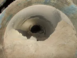
There are several indicators that transport velocity may be insufficient. The most obvious is visible accumulation or plugging within the ductwork (Figure 1). If a section of duct is completely plugged, airflow is effectively eliminated and further investigation is required.
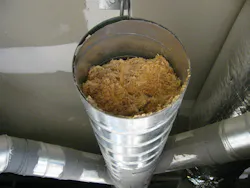
Partial plugging (Figure 2) is often a sign that airflow is insufficient for the installed duct size. This can occur when overall air volume is too low or when ductwork has been oversized for the application, resulting in velocities that are unable to keep material in suspension.
Balancing air volume, duct size, and airflow velocity
To better understand why this occurs, it is helpful to look at the relationship between three key variables: air volume (CFM), duct cross-sectional area, and air velocity (FPM). How these values interact determines whether a system can maintain adequate transport velocity and perform as intended.
Air volume refers to the amount of air moving through the system. Much like a water meter measures how much water flows through a pipe over time in gallons per minute (GPM), air volume describes how much air is moving through the ducting system in cubic feet per minute (CFM).
From a design perspective, air volume is based on system demand, similar to how a plumbing system is sized based on its fixtures. In a dust collection system, this includes equipment connections, hood design, and process conditions. The key point is that air volume is a calculated value, not something assumed or based on a guess. These values can be obtained from equipment manufacturers or technical references such as ACGIH’s Industrial Ventilation: A Manual of Recommended Practice.
Selecting the right velocity for different materials
Unlike air volume, transport velocity is not calculated directly. Instead, it is selected from established guidance such as ACGIH’s Industrial Ventilation: A Manual of Recommended Practice (Figure 3) or SMACNA’s Round Industrial Duct Construction Standard. These references provide recommended velocity ranges based on the material being conveyed.
It is also important to recognize that both insufficient and excessive transport velocities can create issues. If velocity is too low, particles will settle out of the airstream and accumulate in the ductwork. If velocity is too high, it can lead to increased energy consumption, material damage, and accelerated wear on ducting due to abrasion from transported materials. The goal is to operate within the appropriate range for the material being conveyed.
Duct sizing: applying air volume and transport velocity
With these two inputs (air volume and transport velocity), ductwork can be sized appropriately. Duct sizing is determined by dividing the air volume (CFM) by the transport velocity (FPM), which results in the required cross-sectional area.
In practice, this calculated area rarely corresponds exactly to a standard duct size. As a result, duct diameters must be selected from available sizes, which is where the recommended velocity range becomes important. The selected duct size should maintain transport velocity within the appropriate range, and typically toward the upper end of that range to account for system variability over time.
For example, if a system requires an air volume of 4,000 CFM and a transport velocity of ~4,000 FPM, the required duct cross-sectional area would be:
4,000 CFM ÷ 4,000 FPM = 1.0 ft²
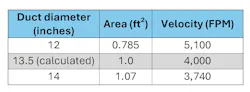
This comparison highlights how changes in duct size directly impact transport velocity, and the importance of ensuring the final velocity remains within the acceptable range for the material being conveyed.
Designing for long-term performance and system reliability
As a dust collection system ages, factors such as wear, buildup, and system changes can reduce airflow and, in turn, transport velocity. If velocity drops below the required range, material will begin to settle and accumulate within the ductwork. For this reason, duct sizing should ensure that adequate transport velocity is maintained not only at startup, but throughout the life of the system.
In the end, transport velocity is not just a technical detail, it is a fundamental factor in determining whether a dust collection system performs as intended. Properly calculating air volume, selecting appropriate velocity ranges, and sizing ductwork accordingly helps ensure that dust remains suspended and out of the system.
About the Author

Diane Cave
Regional manager of Eastern Canada at Element6 Solutions
Diane Cave is Eastern lead at Element6 Solutions. She has more than 20 years of experience working with the design, installation and retrofitting of dust collection systems in industries ranging from sawmills and grain installations to food and beverage and specialty chemicals. Her expertise covers all aspects of dust collection systems, from troubleshooting system issues to upgrading systems to meet current codes and standards. Diane has also assessed hundreds of dust collection systems for combustible dust hazards using the latest NFPA codes and standards and conducted her fair share of DHAs. She can also provide advice and design experience for explosion protection systems, vessel retrofits, Pred verification, static bonding/grounding, and vessel strength analysis. Diane has a degree in chemical engineering from Dalhousie University in Halifax, Nova Scotia.