Choosing the right packing: A comprehensive guide for static and dynamic applications

Compression packing is a critical sealing element in numerous types of industrial equipment. It plays a vital role in preventing fluid leakage, reducing fugitive emissions and ensuring operational safety and efficiency. However, improper selection or installation of packing materials can lead to premature failure, increased maintenance requirements and costly downtime.
Therefore, it is important to have a comprehensive overview of the criteria influencing material choice, the most common types of valve stem packing, their appropriate applications and proper installation practices for compression packing in valves.
Understanding equipment requirements
The selection and installation of compression packing begins with identifying the type of motion involved. At a high level, applications are classified as either dynamic or static, depending on how the equipment operates.
Dynamic applications
Dynamic applications involve continuous or frequent shaft movement, typically at moderate to high speeds. This motion generates friction and heat, requiring packing that can withstand constant motion while maintaining a tight seal. Examples of dynamic equipment include:
- Centrifugal and other types of pumps
- Mixers and agitators
- Blenders and rotating process equipment
These setups demand packing materials that balance between sealing performance, heat dissipation and long-term durability under mechanical stress.
Static applications
Static applications, by contrast, involve slow, infrequent or no movement at all. The most common static applications are valves. In these applications, packing must provide reliable sealing despite pressure fluctuations, temperature cycling and chemical exposure. Examples include:
- Isolation valves (e.g., gate, globe, ball valves), which are typically actuated infrequently.
- Control valves, which operate at low speeds and short strokes. As they may cycle frequently, they are placed in a unique subcategory of static applications that demands special attention.
- Inspection ports, manway covers, tank nozzles and similar equipment that may involve zero movement.
Note: In manway inspection ports and similar access points, the sealing environment is often completely static and may not involve a traditional stuffing box. These are considered special cases. While compression packing can sometimes be used, gasketed seals or form-in-place materials are often more appropriate when dealing with zero-motion environments under pressure or vacuum.
Each equipment type presents distinct mechanical and thermal challenges. Dynamic equipment generates heat and mechanical wear through continuous motion but typically has very low pressures. Static equipment must resist much higher pressures, and often more aggressive chemical attacks, despite minimal movement.
Accurately identifying the type of motion involved is critical to selecting packing that will perform reliably in service. It ensures the chosen material and construction align with the application's mechanical stresses, sealing demands and operating conditions.
Key operating parameters
Packing selection should be based on three primary operating parameters:
1. Temperature
Temperature considerations include both the process (media) temperature, and, in dynamic applications, the frictional heat generated at the shaft-packing interface.
The packing must be able to withstand the media temperature without chemical or physical degradation. In dynamic equipment, friction from shaft movement can create localized hot spots. If not properly managed, this can lead to thermal glazing (vitrification), hardening or even burnout of the packing. In static applications, where there is little or no movement, frictional heat is not a concern — the process temperature matters the most.
2. Pressure
The packing must be able to withstand the internal system pressure without extruding, deforming or losing its sealing integrity over time.
Operating pressures are often higher in static applications, such as valves. To maintain a proper seal, the packing relies on increased gland load, the mechanical force applied to compress the packing and energize the seal. As pressure increases, so does the demand on both the packing material and the gland design.
In dynamic applications, system pressures are generally lower, but the packing must still maintain sealing performance while accommodating shaft movement and resisting pressure-driven leakage.
3. Shaft speed
In dynamic applications, shaft surface speed is a critical factor that directly affects heat generation, packing wear and lubricant loss. Higher speeds increase friction at the packing interface, which can lead to glazing, hardening or accelerated degradation if the packing material is not suited for the conditions.
The shaft surface speed (also called peripheral or linear speed) is calculated using the formula:
Where:
- D = Shaft diameter in millimeters
- RPM = Shaft rotation speed
4. Media compatibility
Packing must be chemically compatible with the process media it will be exposed to — whether it is a gas, liquid, slurry or vapor. Incompatible materials can lead to degradation, swelling, hardening or loss of sealing performance due to binder or lubricant breakdown. Common challenges include:
- Strong acids or alkalis that can degrade natural fibers or organic binders.
- Hydrocarbons that may soften or swell certain synthetic materials.
- Oxidizing agents that attack graphite unless properly inhibited.
- Abrasive media (such as slurries or fluids with suspended solids), which can cause rapid wear and erosion of soft packing materials.
Media compatibility is especially critical in applications involving hazardous fluids, corrosive chemicals or high-purity systems, where a failure could lead to safety risks, contamination or environmental exposure.
Expanded PTFE packing styles (e.g., Teadit 2005, 2006, 2007, 2261 SAN) generally offer the broadest and best chemical resistance. Carbon fiber and graphite-based packing (e.g., Teadit 2002, 2202, 2235, 2236) follow, offering excellent media compatibility along with higher temperature limits.
In abrasive service, phenolic fibers or aramid-blended packing (e.g., Teadit 2004, 2017, 2030, 2774, and 2773) styles are typically recommended due to their excellent abrasion resistance and mechanical durability.
Additional considerations
Finally, it is essential to assess shaft eccentricity, inspect for pitting, corrosion or dimensional wear in the stuffing box, and ensure the stuffing box is dimensioned correctly. Often, failures can be traced to incorrect packing sizing.
Application-specific packing recommendations
General service valves
Typical media: Water, steam, air, mild process chemicals, light hydrocarbons.
Recommended packing:
- Synthetic yarns (e.g., acrylic) for moderate temperatures and pressures.
- Flexible graphite for better performance at elevated temperatures.
- Expanded PTFE styles for outstanding chemical resistance.
Low-e service
Typical media: Water, steam, acids, caustics, solvents, aggressive chemicals (except strong oxidizers)
Recommended packing:
- Flexible graphite with reinforced PTFE-mesh
- Flexible graphite and Inconel filament jacket
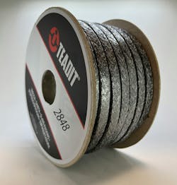
- Examples include TEADIT’s 2236 and 2848
Chemical service
Typical media: Acids, caustics, solvents, aggressive chemicals
Recommended packing:
- Expanded PTFE for the broadest chemical resistance
- Carbon/graphite (Inhibited) for higher temperature chemical exposure
High temperature/steam service
Typical conditions: Steam, thermal oils, heat transfer fluids, superheated media
Recommended packing:
- Flexible graphite packing styles
- Inconel reinforced graphite for high-pressure, high-temp service
Control valves & low-travel actuated valves
Service type: Frequent, low-stroke actuation
Recommended packing:
- PTFE knitted graphite for frequent actuation
- PTFE for the broadest chemical resistance, as long as the temperature is relatively low
- Low-friction flexible graphite for higher temperatures
Note: Live-loaded systems may be beneficial in certain environments with thermal cycles
Abrasive or slurry service
Typical media: Slurries, pulp stock, fluids with suspended solids
Recommended packing:
- Strong synthetic fiber-based packing styles, such as aramid or phenolic fibers
- If both low friction and resistance are required, blended packing styles (such as aramid/graphite blends)
- Phenolic fibers for a good balance of chemical resistance and mechanical strength
- Avoid soft packing styles that are prone to erosion or extrusion
While these recommendations provide a helpful starting point, packing selection is rarely one-size-fits-all. Every application involves a unique combination of pressure, temperature, motion, media and equipment conditions. When in doubt, consult with the packing manufacturer or refer to detailed compatibility and performance data. That said, the guidelines above should help narrow down suitable options in the most common industrial scenarios.
Recommended packing for specific applications
By matching packing style to the application conditions, operators can reduce inventory, improve uptime and enhance safety. Maintenance personnel and operators should also avoid blindly replacing competitor packing. Even ‘equivalent’ products may not suit the actual conditions. A reassessment often reveals materials or constructions that enhance sealing, reduce friction or lower maintenance costs.
Proper installation procedures
Achieving a long-lasting and reliable seal does not end with material selection, it depends heavily on proper installation. Improper handling or shortcuts during installation can lead to premature leakage, packing failure and equipment damage.
While some fundamentals are shared, installation procedures differ between static and dynamic equipment due to differences in motion, gland load and consolidation behavior.
1. Remove old packing
- Fully depressurize and cool the system before beginning.
- Remove all remnants of the previous packing — never reuse old rings.
- Thoroughly clean the stuffing box and inspect for wear, scoring or pitting.
- Check for burrs, sharp edges or shaft misalignment.
2. Measure correctly
To calculate the packing cross-section: Cross — Section (S) = Stuffing Box Diameter — Shaft or Step Diameter ÷ 2
To determine the approximate ring length: L = (1.3 x S + Shaft or Stem Diameter) x 3.14
3. Cut and prepare rings
- Cut rings individually (never install spirals).
- Cut the packing with clean 45° cuts.
- Stagger ring joints at 90° increments during installation.
For static equipment (valves):
4. Install rings sequentially
- Insert rings one at a time, seating each firmly with a tamping tool.
- Lightly tighten the gland follower after each ring.
- For die-formed sets, ensure correct stack height and orientation.
5. Pre-compress and consolidate
- Apply 50% of the manufacturer’s torque value. Close and open the valve. Repeat the process at 100% of the manufacturer’s torque value.
- If possible, cycle the valve under normal conditions to consolidate the packing.
- Re-apply the manufacturer’s torque value after the first thermal cycle or within 72 hours of startup.
For dynamic equipment (pumps, agitators):
4. Install with lubrication in mind
- Insert rings one at a time, seating each firmly with a tamping tool.
- Do not overtighten: dynamic applications rely on slight leakage for lubrication and cooling.
- Minimal leakage (a steady drip rate) is normal and typically necessary.
5. Adjust after break-in
- Run the equipment under normal conditions, then retighten the gland incrementally to reduce leakage without overloading the packing.
- Monitor temperature at the stuffing box — a spike may indicate friction or over-compression.
- Recheck alignment and shaft runout if abnormal wear is observed.
Common errors to avoid
- Installing packing in a continuous spiral rather than individual rings
- Using incorrect dimensions (metric/imperial mismatches)
- Failing to clean the stuffing box thoroughly
- Over-tightening, leading to premature wear or overheating
- Selecting packing based solely on equivalent part numbers without proper evaluation
Final thoughts
Effective sealing begins with the proper understanding, selection and installation of compression packing. By considering equipment type, operating parameters, media characteristics and installation best practices, maintenance professionals can extend equipment life, reduce emissions and improve operational reliability. Always consult with packing manufacturers for specialized or severe applications.
Compression packing may look like a relatively simple component, but it is deceivingly complex. A methodical approach, rather than relying on substitution or outdated habits, can lead to meaningful improvements in system performance and cost efficiency.
About the Author

Angelica Pajkovic
Client Specialist at Teadit
Angelica Pajkovic is a Client Specialist at Teadit, with a particular focus on technical content development. Hailing from Toronto, Canada, she has over six years of experience in the industrial industry. In her previous role as Editor-in-Chief at an industrial B2B Publishing company, she gained a rounded understanding of the challenges, interests, and business relationships in the industrial sector. For more information, please contact Angelica via email at: [email protected].

Julia Köder
Application Engineer at TEADIT International Produktions GmbH
Julia Köder is an Application Engineer at TEADIT International Produktions GmbH. Her responsibilities include providing technical consultation to clients, conducting training sessions, and offering support for technical inquiries. Before taking on this role in July 2022, Julia worked as a project engineer in the automotive section, a position she held from October 2019 after completing her master’s degree in mechanical engineering.


