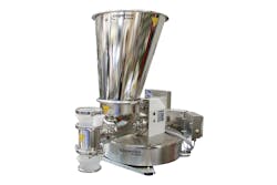
As various industries including the pharmaceutical industry continue to investigate and use continuous manufacturing practices, the roles of loss-in-weight (LIW) feeders and the accurate and consistent refill of these feeders are critical to the overall process. The method of refill, reaction time of the refill device as well as the size of the refill hopper are all critical variables in ensuring an accurate and consistent flow of material to the LIW feeder.
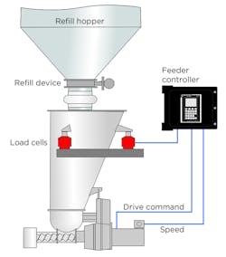
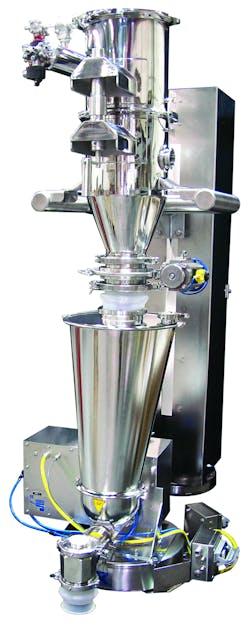
A typical LIW feeder functions by weighing the entire feeder, including the hopper and the material contained in it (see Figure 1.) The speed of the metering device is controlled to result in a per-unit-time loss of system weight equal to the desired feed rate. As the material is fed into the process, the feeder hopper must be refilled again periodically. In continuous processes, it is critical to keep the feeder supplied with material to ensure a consistent output. Such applications include continuous extrusion (both hot melt and granulation extrusion), continuous blending and continuous coating operations.
Figure 1. Loss-in-weight feeder elements.
Refilling the feeder hopper
Two basic ways exist to refill the feeder hopper: the manual method and the automated method. In the manual method, a quantity of bulk solids is tossed into the feeder hopper by the plant operator and the process continues. In the automated method, a refill device above the feed system will add material to the feeder hopper from an upstream supply based on signals from the feeder controls.
During refill, the weight of the feed system is increasing and therefore loss-in-weight feeding is not possible. In the past, the traditional method of maintaining feed during refill was to simply use a constant volumetric metering speed throughout the refill phase — a speed corresponding to the metering speed associated with gravimetric control just prior to entering the refill phase. If, for example, the metering speed averaged 60 rpm just prior to the system sensing the need to refill the supply hopper, the screw speed would be maintained at that 60 rpm for the duration of the refill operation. After refill is completed, material has settled, and the feeder senses an appropriately declining system weight, the feeder is returned to gravimetric operation where metering speed is once again controlled based on the loss in weight of the feed system.
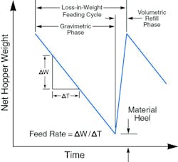
Figure 2 plots the hopper weight versus time, and shows the declining weight signal, the slope of which represents the feed rate (change in system weight per unit time). Note that the hopper does not empty completely before the refill phase is triggered. The prime reason for this is to ensure an ever-present supply of material at the metering device so feeding may proceed without interruption. Additionally, if a sufficiently large material heel is not present, the increasing pressure applied by the impact of the incoming and possibly aerated material during refill may cause uncontrolled flooding through the feeder.
Even with an insulating heel of material in place, density within the metering zone will rise somewhat as the hopper fills. Given a constant metering speed during refill, this increase in density causes aggressive degradation in feeding accuracy (overfeeding) as more and more material enters the hopper and compacts the material into the feed screw intake.
How severely does this affect accuracy? The answer hinges on hopper size/geometry in addition to the compactability of the material itself. Laboratory tests and field experience involving many hundreds of materials show that, in practical terms, headload-related loss-in-weight overfeeding may range between +/- 1 percent for relatively constant-density materials. However, for powders and other materials with density that can vary substantially, this can fluctuate as high as +/- 10 to 15 percent.
Figure 2. Loss-in-weight operating principle
The smart refill concept
As shown in Figure 3, the use of constant speed and incorrect assumptions on the effects of varying density during refill can have a significant negative effect on the resultant feeder accuracy. Therefore, a controlled method of storing and trending the weight-to-speed relationship was developed to avoid these problems. This method, referred to as Smart Refill Technology (SRT), discards the approach of maintaining a constant metering speed. During normal operation the feeder control system stores data-correlating system weight, screw speed and other parameters. During automated refill, the feeder control system switches to volumetric control, but uses the data obtained while the hopper was emptying product to determine what screw speed is required for an accurate feed rate based on feed system weight.
SRT enables metering speed to be gradually adjusted during refill to precisely counterbalance the effects of increasing material density occurring within the metering zone as the hopper weight increases. The slower rate is determined by storing in the controller’s memory an array of indices, called Feed Factors. These values correspond largely to material density and its mechanical behavior within the feeder, and they are computed during the entirety of the gravimetric feeding cycle. Then on the basis of sensed hopper weight at each array point during refill, material density within the metering zone may be inferred, and a metering speed corresponding to its Feed Factor array value may be correlated. In this way, gravimetric feeding accuracy during the brief refill may be maintained.
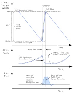
The SRT approach is most easily illustrated by considering Figure 3. The graph at the top plots net hopper weight versus time. Beginning with a full hopper (where net hopper weight equals refill complete weight) gravimetric operation is in effect and the feeder operates normally according to the operating principle explained above. However, as net hopper weight declines, the controller also determines and stores a set of up to 100 feed factors, each of which is the index of the average density of material discharged at the hopper weight associated with the feed factor. A low feed factor indicates that a higher number of screw revolutions were required to discharge a given weight, implying a reduced material density. Conversely, a higher feed factor reflects higher density since fewer revolutions were required to deliver the same material weight.
Figure 3. The smart refill concept
The middle plot of Figure 3 shows motor speed versus time. During the early portion of the gravimetric feeding phase motor speed is relatively constant since density within the metering zone of the feeder, while higher than at later times in the feeding cycle, does not vary substantially. This is because material in the upper portion of a typical hopper is largely supported by the material below, and, in turn, the tapering walls of the lower portion of the hopper. As feeding proceeds and hopper level declines, headload in the metering zone begins to lessen, resulting in a reduction in density and a corresponding increase in motor speed required to maintain feed rate. When hopper weight reaches the refill request threshold, the refill phase begins. During refill, SRT begins with the motor speed that was in effect at the time of the refill request, and then modifies that speed by applying the corresponding feed factor as each hopper weight "slice" is encountered.
Figure 4
What refill interval is deemed acceptable?
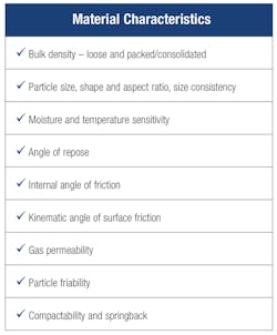
As a rule, the refill period should be about 6 to 10 seconds. This duration ensures positive control over the incoming material but is so short that minor flow variations should not perturb the downstream processes. However, it is imperative that a study of the bulk solid properties, as outlined in Figure 4, be made when dealing with refill issues.
Each of these material characteristics will greatly affect not only the flow out of the hopper but also how quickly the hopper is refilled. For example, if the bulk material has a high gas permeability (i.e., if gas can escape rapidly from the solid), the refill can occur as rapidly as is feasible. On the other hand, if the bulk material has a very low permeability rate (i.e., the gas expands the bulk material and doesn’t quickly escape to return the solid to its resting condition), care must be taken during refill, for often these materials become floodable in this condition or at least suffer significant bulk density changes.
If flooding of the bulk solid begins during refill, the product could easily flush out of the loss-in-weight feeder. At a minimum, air entrainment effects resulting in underfeed conditions during and immediately after refill can significantly alter bulk density, since the control system is using control data from earlier in the run, when the product density was much higher. Air entrainment comes from rapidly refilling the feed hopper, such that air, being unable to quickly escape, passes through the incoming material to the region of lower pressure above in the refill hopper. Venting of the weighed hopper can minimize the problem, but now dust collection and, in the case of active materials, filtration, must be arranged. Adequate venting will assist in material settling and aid in a quicker return to true gravimetric operation.
Table 1
Refill hopper sizing
Another issue that often arises with refill systems is determining how often the feeder should refill to get the best performance. This also is dependent upon properties of the material, in how well behaved the bulk solid is when it is being transferred from the refill bin to the weighed hopper, and how responsive the weight measurement system will be to react to rapidly changing weight values that occur when frequent refills occur. If the system is refilled more frequently, the feeder is spending more time in volumetric control.
However, if headroom and space are not an issue, the weighed hopper can be larger, thus minimizing the time the feeder spends in volumetric control. The longer the feeder is in volumetric control, the more likely it will drift away from delivering the desired setpoint. Table 1 outlines some of the benefits and challenges of refill hopper sizing.
Figure 5. Coperion K-Tron P-Series vacuum receiver refilling a Coperion K-Tron LIW pharmaceutical feeder
Selection of the refill device
There are several choices for the type of refill device used above the feeder hopper. Options include knife gates, modulating butterfly valves, rotary valves or in the case where extreme control is required, such as in microfeeding, metered devices such as volumetric screw feeders. In addition, pneumatic loaders/receivers are often used above the butterfly valve or rotary airlock to refill the feeder hopper, as shown in Figure 5.
A knife gate or a slide gate might be acceptable if the feeder hopper is large and consumes most of the vertical space between the weighed hopper and the refill hopper, and if modulation of the gate valve is feasible for the given bulk material flow characteristics. Problems arise when the refill system does not take into consideration the capacity of the feeder hopper, the flow properties of the bulk solid, and the distance and potential storage volume of bulk solids that can occur between them.
For example, in refilling a feeder hopper from an intermediate bulk container (IBC), super sack, or large hopper, the volume of the product in these vessels will often exceed the volume of the feeder hopper. Clearly, it is impossible to control the refill without overfilling the feeder hopper, unless a time window is established for the opening and closing cycle of the refill valve. This time window can be calculated based upon bulk density of the material, the angle of repose that dictates the settling leveling the feeder hopper, and the flow rate through the refill device. It should also be noted, that when discharging from bins or IBCs, which may be equipped with flow aid devices (e.g., vibrators or live bottom bins), that special care must be made to isolate the vibration of these devices from the feeder hopper, to ensure that there is no interference on the loss-in-weight feeder weight measuring device.
A rotary valve can also be used to isolate pressure zones from the weighed hopper. When using a rotary valve, the vanes must be tightly sealed and at least eight to 12 vanes used. If this is the case, an additional refill valve is usually not required. The rotary valve is a good choice for handling floodable and free-flowing powders since it meters them in a controlled manner to the weighed hopper. However, special care should be taken if the powders are not free flowing or cohesive, as they may tend to agglomerate or pack in the rotary valve vanes.
As stated previously, the flow rate from the refill device must be sufficient to avoid exceeding the refill time limit. Additionally, the flow cutoff action of the selected device must be quick and sure. A slow tapering off of the refill flow needlessly lengthens refill time, and any leakage of the refill device may cause an unavoidable measurable weight disturbance, but will always result in a flow error in the positive direction.
Pneumatic vacuum receivers as refill devices
Pneumatic receivers that operate under a dilute phase vacuum transfer principle are often used as refill devices, particularly for continuous operations. The pneumatic system uses negative pressure to suck the material required for refill into a separately mounted and supported vacuum receiver. The receiver is filled to a determined level and then holds this material charge until the feeder below requests a refill. The level of fill in the receiver is determined by level sensors. At the point of refill request by the feeder below, the discharge valve opens and the receiver contents are discharged into the feeder hopper. At the same time of this release, a gas pulse is sent through the filter housed in the vacuum receiver to release any entrained particulate or material that may have settled on the filter. The filter material can vary, including options on laminated membrane type materials, for quick-release and easy-clean properties.
After dumping the material into the feeder hopper below, the valve is shut again and then the receiver vacuum cycle immediately begins for the pneumatic receiver to be instantly ready for the next refill request. The use of pneumatic receivers as refill devices allows for an uninterrupted source of refill from either bags, drums, IBCs or supersacks.
Summary
The combination of both the Smart Refill Technology and highly accurate load cell technology allows for the most advanced combination in loss-in-weight feeding and refill operations. Through careful evaluation of the feeding process, layout of the system and material characteristics, a truly economical, efficient and optimal continuous feed and refill system can be provided.
Sharon Nowak serves as global business development manager for the food and pharmaceutical industries for Coperion and Coperion K-Tron. Nowak has more than 30 years of experience in the process equipment industry for food and pharmaceuticals and a degree in chemical/biochemical engineering from Rutgers University. She has extensive experience designing and integrating feeders and material handling equipment including pneumatic conveying into continuous and batch processes for food and pharmaceuticals including blenders and mixers, mills and micronizers, extruders, granulators and coaters, and contained processes for potent pharmaceutical compounds.
