Blowdown analysis delivers accurate results for depressurizing
Whether in an emergency or on a planned basis, depressuring a process plant, commonly referred to as "blowdown," is a critical-to-safety operation for today’s industrial plants. It might be required in the event of a fire, leak, pipe rupture or other hazard, or for a planned shutdown. During depressuring, control and safety valves, relief valves, restriction orifices, and rupture disks are involved in transferring the potentially dangerous contents of process equipment to a safe, lower-pressure location, or to a flare system for controlled combustion.
Software-based design simulation models the depressuring behavior of process equipment, thereby supporting good design decisions. However, many tools assume phase equilibrium, which can lead to inaccurate predictions with consequences from potentially dangerous under-designs to unnecessarily costly over-designs.
Recently introduced blowdown software addresses these shortcomings using non-equilibrium models. For example, the blowdown utility in Honeywell’s UniSim Design incorporates a rigorous vessel-unit operation with non-equilibrium holdup calculations; simultaneous solution of model equations; and a clear, straightforward interface to configure the model. Moreover, it is validated and tuned against both proprietary and open-literature experimental data.
Blowdown background
For modern industrial facilities, blowdown procedures are essential for protecting plant assets against the effects of high pressures or temperatures. Pressure vessels, heat exchangers, distillation columns, compressors and other equipment operate safely within an operating window reflecting the design pressure and temperature, but constitute a significant safety hazard if run outside established boundaries.
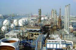
To take a single example, pressurized equipment is found in oil refineries where process variables are often pushed to design limits, as refiners maximize parameters such as gasoline and diesel production. Pressure vessels are employed in services ranging from feed and product storage to reactors, separators and fractionation towers.
By definition, a pressure vessel holds gases or liquids at a pressure substantially different from ambient pressure. The consequences of its failure can be fatal. The pressure differential defines a point of danger, and many serious accidents occur involving high-pressure equipment operation.
A process plant is typically divided into a number of independent blowdown segments. The blowdown of the entire facility entails simultaneously or sequentially depressuring all pressurized gas or liquid in each facility segment.
During separator depressuring, for example, the vessel’s inlets and outlets, whether gas, liquid or water, are blocked by closing isolation valves, also called emergency shutdown valves (ESDVs).
Gas is directed to the flare or vent through an isolation valve and restriction orifice, pressure relief valve, bursting disk or manual valve.
Concerns and considerations
The rapid vapor generation and expansion of gas during emergency depressuring can expose pressure vessels and other equipment to pressurized thermal shock. This is caused by combined stresses from rapid temperature or pressure change and results in non-uniform temperature distribution in the vessel walls and their subsequent differential expansion and contraction. Pressurized thermal shocks can also cause embrittlement of vessel metal walls, leading to failure by fatigue.
For safe use of a pressure-relief and blowdown system, important factors include construction material selection, especially concerning low temperatures; sizing of relief valves, orifices, piping and vessels; and choosing connections and determining the capacity of the flare system.
In greenfield plants, an accurate prediction of the minimum vessel-wall temperature during blowdown can impact selection of construction materials, reduce over-design and consequently lower project cost.
Similarly, accurate prediction of maximum flow rate during blowdown reduces the over-design often associated with a relief valve or network without compromising safety. For brownfield plants, blowdown studies can lead to operating-procedure changes as well as to process equipment materials or capacities to minimize the likelihood of brittle fracture.
For accurate predictions, software simulation tools model process equipment depressuring behavior to answer the following questions:
- At what rate must gas be released from each item to meet required depressuring times?
- What is the required total-flare capacity?
- What is the lowest metal temperature experienced in each equipment item and in the flare system?
- Which low temperature materials are required?
- What size-restriction orifice or other flow-rate controlling device and flare connections will depressure each section of the plant?
Industry already has software tools for dynamic simulations of blowdown events and, in turn, for depressuring and gas-rate profiles used in analysis. These utilities can simulate vessel and pipeline depressurization, or the combination of several connected vessels and pipe volumes through a single valve.
However, simulation tool accuracy varies significantly depending on the fidelity of the modeling approach. Predictions are often inaccurate due to simplifications in mathematical models. Additionally, depressurization is a non-equilibrium process that has not been properly represented in most commercially available depressurizing utilities.
Companies with critical concerns about equipment blowdown need effective calculation and simulation solutions to determine:
- Minimum temperatures throughout the process and pipework metal walls
- Blowdown times and relief loads entering the flare network
- Valve sizing, including blowdown valve sizes
- Fluid temperature typically entering a flare system that might contain evaporating entrained
liquids
Latest technology advancements
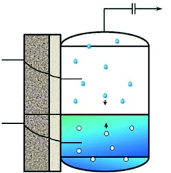
Figure 1: The latest blowdown software enhancements include an accurate holdup model for non-equilibrium three-phase systems. Courtesy Honeywell
Recently introduced blowdown software achieves improved fidelity by a modeling approach consistent with recommended practices set out in the sixth edition of the American Petroleum Institute (API) 521 Guide for Pressure Relieving and Depressuring Systems. These include the following:
- Simulates equipment emergency depressuring within a flow-sheet environment
- Rigorously handles non-equilibrium three-phase systems
- Uses a variety of rigorous thermodynamic models
- Improves heat-transfer modeling across metal by incorporating better correlations for heat-transfer coefficients
- Incorporates rigorous formulas for volumes, and for surface and interfacial areas
- Evaluates different configurations of vessel orientations
The latest blowdown technology, compared with experimental data, is a strong match for fluid- and wall-temperature predictions, especially on horizontal vessels. The software is intuitive and easy-to-use, clarifying and simplifying required input while remaining numerically robust, and with no reported cases of unexplained trends. It features detailed descriptions of vessel dished heads and integrates two wall material layers and two insulation layers (see Figure 1).
Typical user benefits
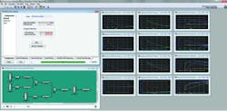
Courtesy Honeywell
With blowdown design simulation technology, vessel depressuring behavior can now be accurately predicted, improving pressure vessels, relief devices and relief/flare systems. This increased accuracy improves intrinsic safety.
A state-of-the-art blowdown tool enables improved prediction of the maximum flow rate through the relief device. Coupled with knowledge of the lowest metal temperature experienced, more reliable and accurate sizing of pressure vessel, relief devices and relief/flare systems is possible.
Finally, blowdown simulation tools are simple and user-friendly, reducing the effort needed for engineers to run case studies. Ongoing blowdown utility enhancements will support multiple-vessel modeling with interconnecting piping in an equation-based modeling (EO) environment. Users can more accurately predict temperature profiles in vessels and surrounding piping, integrate blowdown scenarios with the process and configure the flow-sheet to achieve optimization with a single utility.
Plant personnel can make accurate predictions, despite the non-equilibrium nature of a pressure vessel, as regards different vapor and liquid temperatures, which legacy tools do not distinguish. By eliminating the need for adjustable parameters in the model, fewer user inputs are needed. While this solution does not account for the solid phase in the model, it can accurately predict the incipient solid CO2 and hydrate formation temperature.
J. A. Barber is a principal engineer with UniSim Design After Market Services at Honeywell Process Solutions, and V. Athanasiou is the global product manager for process design at Honeywell.