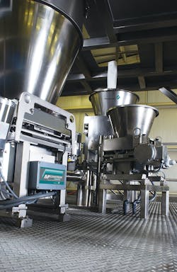
Gravimetric, or loss-in-weight, feeders are frequently used in continuous manufacturing processes. A gravimetric feeder relies on a control system that adjusts the speed of the feeder based on loss-in-weight measurements. Because the controller is unable to measure the solids discharge rate when its hopper is being filled with new material, two hoppers arranged in series are typically used. During the fill cycle, the downstream feeder is operated in a volumetric mode (i.e., at a constant speed). The feeder then operates in gravimetric mode (i.e., its speed is controlled by measuring the loss in weight of material inside the hopper and feeder) after the downstream hopper has been filled. A schematic of a gravimetric feeder is given in Figure 1.
To reduce the likelihood of flow obstructions, the lower extension hopper is typically a cylinder or an asymmetric cone with one vertical wall. Unfortunately, for these geometries, the solids stress will decrease as the material level inside the hopper decreases, and because powders are generally compressible, the bulk density will drop as a result. Consequently, the feeder speed must be increased to maintain the set point discharge rate. This is not a problem when the feeder is operated gravimetrically, but during the fill step, the loss in weight cannot be measured. If an additional stress were applied to the powder, for example, if a slug of powder were dropped rapidly from the upper hopper into the lower hopper, the stress would be transmitted vertically, further increasing the bulk density of the powder in the feeder. The feeder would be unable to compensate for the change in bulk density because it was in volumetric mode during the fill cycle.
There are methods to dampen the variability of the discharge rate. For example, fresh powder can be added more frequently to reduce the amount of time the feeder is operated in volumetric mode. Also, modern controllers are more predictive in that they can estimate the higher bulk density that accompanies the fill step, which allows an estimate of the required feeder speed while in volumetric mode.
A better strategy is to ensure that the solids stress in the feeder will remain constant. With a constant solids stress, the bulk density of the powder inside the feeder will remain the same, and the set point can be maintained during the fill stage.
Solids stresses are well understood. In a cylinder, the solids stress profile is asymptotic and can be predicted from the Janssen equation:1
(1)
where σv is the average vertical solids stress, k is the ratio of the wall stress to the vertical stress, (approximately equal to 0.4 for cylinders), RH is the hydraulic radius (i.e., the ratio of the cross-sectional area to the perimeter), ρb is the bulk density, g is acceleration due to gravity, and z is the depth of solids in the cylinder. If an average value of the bulk density ρb is used and there is no external stress applied to the powder, Equation 1 can be integrated to give the more familiar form of the Janssen equation:
(2)
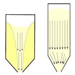
The solids stress profile in the converging section of the extension hopper can be readily calculated if the flow pattern is mass flow. Mass flow occurs when the walls are sufficiently steep and wall friction is low enough to allow flow along the walls. If not, funnel flow will take place in which flow of solids only occurs in a narrow channel above the hopper outlet. Solids flow patterns are illustrated in Figure 2.
The hopper angle required to allow mass flow is determined by measuring the friction between the powder and the hopper wall material. Wall friction is measured by applying various normal loads to a sample of powder and forcing it to slide along a coupon of wall material. The resulting shear force is measured as a function of the applied normal force, and a wall yield locus is constructed by plotting shear force against normal force. The angle of wall friction ϕˊ at a particular pressure is the angle that is formed when a line is drawn from the origin to a point on the wall yield locus. A sample yield locus is given in Figure 3.
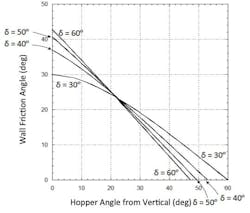
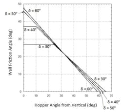
Jenike2 developed design charts that provide allowable hopper angles for mass flow given values of the wall friction angle and the effective angle of friction δ, which is determined by shear cell testing. The design charts provide allowable hopper angles for mass flow given values of wall friction angle and the effective angle of friction. These charts are shown in Figures 4 and 5 for conical (or pyramidal hoppers with square outlets) and planar hoppers (e.g., wedge-shaped, chisel, and transition hoppers), respectively. The outlet of a wedge-shaped or transition hopper must be at least two times as long as it is wide for Figure 5 to apply if it has vertical end walls and three times as long if its end walls are converging.
Values of the allowable hopper angle for mass flow θˊ (measured from vertical) are on the abscissa, and values of the wall friction angle ϕˊ are on the ordinate. Any combination of ϕˊ and θˊ that falls within the mass flow region of the chart (i.e., to the left of the boundaries) will provide mass flow.
Hoppers with round or square outlets should not be designed at the theoretical mass flow hopper angle value. Otherwise, a small change in the bulk material’s flow properties may cause the flow pattern inside the hopper to change from mass flow to funnel flow. A 2 to 3° margin of safety with respect to the mass flow hopper angle given in Figure 4 is therefore recommended. Sloping walls required for mass flow in planar hoppers can be 10 to 12° less steep than those required to ensure mass flow in conical or pyramidal hoppers.
An analytical equation of the theoretical boundary between the mass flow and funnel flow regions for conical hoppers is as follows:3
(3)
where β is calculated from
(4)
A 2-to-3-degree safety factor should be subtracted from the result of Equation 3.
For hoppers with slotted outlets, the following equation can be used to calculate the recommended mass flow hopper angle:4
(5)
In the converging section of the extension hopper, the maximum solids stress are initially directed downward when the hopper is first filled. This is called an active state of stress. When the bulk solid is discharged from the bin, changes in the stress conditions in the hopper section occur. If powder flows as mass flow, the bulk solid will be compressed laterally and expand vertically. As a result, the major stresses will be directed horizontally instead of vertically. This state of stress is called the passive state. The solids stress profile in the converging section of a mass flow hopper can be calculated from:5
(6)
where
(7)
where θˊ is the hopper angle (from vertical) and m is equal to 1 for a conical hopper and equal to 0 for a straight-walled hopper having a slotted outlet. The stress constant k can be calculated from equations given in the Eurocode6 and ranges between about 2 to 4. If average values of the bulk density and stress ratio are used, Equation 5 can be integrated to give
(8)
where x is the vertical coordinate upwards from the hopper apex, σvht the mean vertical stress on the solid at the transition after filling (as determined by the Janssen equation), and h is the vertical height between the hopper apex and the cylinder-hopper transition.
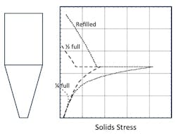
Towards the outlet of the converging hopper, a radial stress field develops, and the stress will be a function of only the radius. As a result, the solids stress at the outlet remains nearly constant. This is the feature of a mass flow hopper that allows the powder inside the feeder to remain constant when the material level inside falls and when the hopper is refilled. In fact, if a small amount of variability in the discharge rate can be tolerated, a less-expensive volumetric feeder can often be used in place of a gravimetric feeder.
The outlet of the hopper must of course be large enough to prevent an arch from forming. The critical outlet dimension depends on the powder’s cohesive strength and bulk density. Design equations exist that calculate minimum outlet dimensions that prevent arching.7 Gravimetric feeders often incorporate agitators to prevent arching above the auger, thereby allowing feeders to have large outlets.
Figure 6 shows the solids stress profile at the end of an emptying cycle and the start and end of a fill cycle. Because the lower hopper is a mass flow hopper, a passive state of stress exists once flow is initiated and remains when the hopper is refilled. As a result, the solids stress at the hopper outlet remains nearly constant as does the bulk density of the powder in the feeder.
If a gravimetric feeder is to be used and a constant solids discharge rate is desired, its extension hopper should be designed to allow mass flow. This ensures a nearly constant solids stress inside the feeder, and a nearly constant bulk density and allows a steady solids discharge rate when the feeder cannot be operated gravimetrically.
References
- Janssen, H.A., Zeitschr. d. Vereines deutscher Ingenieure, 39, 1045 (1895).
- Jenike, A.W., Storage and Flow of Solids, Bulletin 123, University of Utah, 1964 (revised, 1976).
- Jenike, A.W., Gravity Flow of Bulk Solids, Bulletin 108, University of Utah, 1961.
- Arnold, A.W., Bulk Solids: Storage, Flow, and Handling, TUNRA Publications, 1980.
- Schulze, D., Chem. Eng. Sci., 49, 13, 2047 (1994).
- European Committee for Standardization, EN 1991-4:2006.
- Mehos, G., “Using Solids Flow Properties to Design Mass- and Funnel-Flow Hoppers”, Powder Bulk Engr., 34, 2 (February 2020).
Greg Mehos, Ph.D., P.E. is the director of Greg Mehos & Associates LLC and is a chemical engineering consultant who specializes in bulk solids handling, storage and processing and an adjunct professor at the University of Rhode Island. Greg enjoys teaching professionals and students bulk solids engineering fundamentals so that they can solve powder handling problems and design equipment for reliable handling of solids. He has authored dozens of technical papers on the subject and contributed to the Solids Processing and Particle Technology section of the ninth edition of Perry’s Chemical Engineers’ Handbook. He received his B.S. and Ph.D. in chemical engineering from the University of Colorado and his master’s from the University of Delaware. Greg is a Fellow of the American Institute of Chemical Engineers and a past chair of the Boston local section. He is a licensed professional engineer in Massachusetts.
Greg Mehos & Associates
About the Author

Greg Mehos
Greg Mehos, Ph.D., P.E. is the director of Greg Mehos & Associates LLC and is a chemical engineering consultant who specializes in bulk solids handling, storage and processing and an adjunct professor at the University of Rhode Island. Greg enjoys teaching professionals and students bulk solids engineering fundamentals so that they can solve powder handling problems and design equipment for reliable handling of solids. He has authored dozens of technical papers on the subject and contributed to the Solids Processing and Particle Technology section of the ninth edition of Perry’s Chemical Engineers’ Handbook. He received his B.S. and Ph.D. in chemical engineering from the University of Colorado and his master’s from the University of Delaware. Greg is a Fellow of the American Institute of Chemical Engineers and a past chair of the Boston local section. He is a licensed professional engineer in Massachusetts.
