Troubleshooting plugged pneumatic conveying lines

Pneumatic conveying takes many forms and has many applications. Systems range from the pneumatic tubes used at your bank's drive-through windows to the massive systems that unload ships and railcars or move large quantities of material in processing plants. But despite more than 130 years of use, pneumatic conveying is still considered an art by many system designers and users. That said, significant technological progress has been made in the last three decades to help end users both evaluate vendor equipment proposals and troubleshoot and optimize their own installed pneumatic conveying systems. Before getting into troubleshooting, however, it’s important to understand a few things about pneumatic conveying systems and the way we talk about them.
Obtaining data
Pneumatic conveying development and testing, typically done in a test lab environment, is usually based on short-term, small-capacity, small-diameter, short-distance conveying systems. In the US, much of the information discovered this way is considered proprietary and is used to help equipment suppliers obtain a competitive edge. In recent years, that situation has begun to change, with some independent academic and specialty engineering firms offering bench testing and more “real world” conveying line test loops for testing end user’s materials and providing them with the necessary test results to make decisions concerning their existing systems and the planning of new systems. Obtaining data on an installed, full-scale operation remains difficult, however, because most processing plants don't want to halt their operation to run tests on their process equipment.
Communicating clearly
Because pneumatic conveying science falls somewhere between mechanical and chemical engineering, establishing universally accepted or defined terminology has been difficult. Many terms in this article are defined because they can be used differently by different people. (Also, be aware that many pneumatic conveying terms have been coined as part of equipment advertising or sales promotions with no accompanying definitions.)
Simple terms that have been used at least during the 54 years of my career can have two or more meanings such as: pickup velocity, terminal velocity, loading, and flow characteristics.
Pickup velocity. Pickup velocity can mean the superficial gas velocity in the conveying line at the feed point or the gas velocity required to entrain material that has settled on a horizontal line's bottom. The latter velocity is about twice as high as the former.
Terminal velocity. Terminal velocity can mean the free-fall terminal velocity of an object in a gas or liquid or the velocity of material at a conveying line's end (or terminal point).
Loading. Although loading refers to the material-to-air ratio in the conveying system, for application simplicity, this term is often used in one of the following four forms due to the large range of numbers possible (for instance, from 0.2 to 100 pounds of material per pound of air):
- Pounds of material per pound of air.
- Pounds of material per cubic foot of air.
- Pounds of air per pound of material.
- Cubic feet of air per pound of material.
Obviously, it’s important to define what you mean by loading when talking about a pneumatic conveying system to prevent costly misunderstandings.
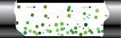
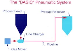
Flow characteristics. The terms for flow characteristics of pneumatically conveyed material include dilute phase (stream flow) in which the material is entrained in the conveying gas (typically air), as shown in Figure 1, and dense phase (two-phase flow, pulsed-piston flow, and so forth) in which some or all of the material is not entrained in the conveying gas. But the exact point at which one of these flow characteristics stops and another starts can't be defined by pressure, velocity, or loading and is, in fact, much more complicated. This article will address troubleshooting a typical dilute phase conveying system (Figure 2).
Attacking assumptions
Because a pneumatic conveying problem usually affects a plant's production rate, it's important to solve the problem as fast as possible. Engineers don't have the luxury of making several tests and modifications to solve a problem but rather are asked to fix it immediately. Given the nature of pneumatic conveying, engineers often decide to fix the problem by using more conveying air, which may overcome the immediate difficulty but may not solve the real problem.
Rules for troubleshooting conveying line plugs
Considering the following rules can help end users troubleshoot line plugging problems in their dilute phase pneumatic conveying systems. These rules can be divided into four categories based on the root cause of the plugging: Conveying air volume, line configuration, air leakage, and miscellaneous causes.
Conveying air volume
It is almost always assumed that using more conveying air will eliminate a line plug, but this isn't necessarily so.
Rule 1. More conveying air won’t necessarily eliminate a line plug. Airflow always moves from a higher pressure to a lower pressure, and this is also true in a pneumatic conveying system, whether it is a pressure system or a vacuum system. Because the air is flowing to a point of less pressure, the air volume is expanding and the air velocity in the conveying line is ever-increasing from the feed point onward. A line plug occurring in the first 50 feet of a conveying system may require a higher conveying air volume. However, if the material was initially entrained at the feed point, the system has adequate air volume and the problem lies elsewhere.
Line configuration
Three rules relate to conveying line configurations:
Rule 2. Avoid a horizontal-to-vertical bend in the system's first 20 feet. If you can't avoid such a configuration, use a short-radius bend (a radius of three to five times the line's inside diameter. A long-radius bend from horizontal to vertical in the system's acceleration zone can cause a line plug or require excessive air velocity to convey the material. The acceleration zone is about the first 20 feet of the system. A horizontal-to-vertical bend in this zone doesn’t allow the material to fully accelerate or become entrained, and material will settle on the bend's sloped section. This material will then slide downward, causing material to accumulate at the bend bottom and possibly start a line plug. A shorter-radius bend or a longer straight section before the bend can help prevent this problem.
Rule 3. Avoid multiple bends in a series. Multiple direction changes in a row require higher air velocities. You can make any direction change with two 90-degree bends. At any place where three bends are located in a series, change the line routing to minimize the bends' energy requirements. If you can't change the routing, try to use an acceleration zone (about 20 feet of straight line) between the second and third bends.
Rule 4. Avoid upward-sloping lines when saltation can occur. An upward-sloping line requires higher air velocities to prevent saltation. This in turn can increase the system's energy requirements and lead to a line plug. Because a sloping line's saltation velocity is greater than that of a horizontal line, it's possible to be in dilute phase in the horizontal line and have saltation in the sloped line. If the line is at an angle greater than about 20 degrees when saltation occurs, the material slides backward down the incline and must be reconveyed, which is called refluxing.
Air leakage
Four rules relate to air leakage:
Rule 5. Check for a worn or leaking line charger on a pressure pneumatic conveying system. If your system used to work well but has developed conveying problems, look for worn equipment. In a pressure conveying system, some air leaks out of the system through the line charger by design. However, a worn rotary airlock/feeder rotor with larger clearances increases that air leakage. Pressure tank inlet and vent valves can also wear and permit air leaks. Screw pump end discharge non-return gates can be worn, or the material seal may be insufficient and not make a positive seal against return airflow.
Rule 6. Check for worn or leaking airlocks on a vacuum conveying system. In a vacuum conveying system, some air leaks through the material discharge device under the filter receiver. A worn airlock rotor increases clearances and air leakage. If the system uses a lock hopper (also called a double flap valve), air can leak if the lock hopper’s seats and gates become worn. You won’t be able to detect any air leakage at the filter receiver because the air leaks directly into the receiver and then to the air mover.
Rule 7. Check for diverter valve leaks. If a line plug forms about 20 to 40 feet after a diverter valve, check that the valve is seating properly and doesn't leak. In a pressure conveying system, a worn or non-seating (not fully closing) diverter valve can cause a line plug. The plug will usually occur about 20 to 40 feet after the diverter valve. Inertia typically causes the conveyed material to follow the straight flow path, but air will leak into the valve's divert leg. Because of the air leak, the material will continue for a distance, then deposit on the line bottom and form a line plug.
Rule 8. Check for air leaks at couplings or in conveying line holes. Air leaks into or out of the conveying line naturally will affect the conveying system. For instance, in a vacuum system, a leaking coupling or hole in the conveying line is difficult to detect. But the leak will reduce air volume at the feed point and cause a line plug in the line’s initial section. In a pressure system, the leak is usually obvious because some material escapes from it. However, if the conveyed material is clean and coarse, such as plastic pellets, it won't leak out. The leak in a pressure system typically forms a line plug a short distance downstream from the leak.
Miscellaneous causes
Six additional rules cover various causes, including dirty filters, plugged dust collectors, relief valves, material buildup, worn air movers, and full receivers:
Rule 9. Regularly clean all air filters. A dirty or partially plugged air filter to a vacuum conveying system or to a pressure system's air supply can greatly reduce the air volume and cause a line plug. This is difficult to detect in a vacuum system unless you monitor the vacuum at the feed point. When the air inlet filter to a fan is clogged, it partially unloads the fan, delivering less airflow at lower horsepower. When the air inlet on a positive displacement blower is dirty, the pressure drop across the blower increases, reducing the airflow and increasing the required horsepower.
Rule 10. Regularly check your dust collector's pressure drop gauge. Ensure that you operate the dust collector within the design pressure drop, usually below 6 inches water pressure. Excessive pressure drop on a pressure conveying system's dust collector or across a vacuum system's filter receiver can reduce the airflow and increase the system's operating pressure.
Rule 11. Check that relief valves have proper seating and don't leak. Improper initial setting, vibration, or operating wear can cause a relief valve on a conveying system to open at too low an operating pressure. If the valve has opened frequently, the seating material may be damaged and no longer airtight.
Rule 12. Check for material buildup or foreign material in the conveying line. Some very fine or moist materials can stick to the conveying line wall, causing a plug. Using flexible-hose line in the material buildup area can help to prevent or minimize this blockage.
Rule 13. Check that the air mover is operating properly. A worn air mover will seldom cause a line plug in a conveying system in which the material doesn't pass through the air mover, as long as the system has proper filtration. But in a pull-push conveying system (a vacuum conveying system that terminates in the fan inlet and, at discharge, changes to a pressure conveying system), where material passes through the fan, the fan wheel will wear and require occasional replacement. Check the fan's rotation direction too. Even if it's rotating in the wrong direction, a fan can create airflow in the desired direction; however, this will reduce the air volume and system pressure.
Rule 14. Check the material level in the receiver vessel. If the conveyed material fills the receiver vessel and blocks the conveying system discharge, a line plug will form. A line plug will also form in a vacuum conveying system if the material feedrate exceeds the receiver vessel's discharge rate. The vessel's material level is difficult to monitor unless you install a level detector in the vessel to indicate when the material level is high and likely to cause a plug.
About the Author

Jack Hilbert
Principal Consultant at Pneumatic Conveying Consultants LLC
Jack Hilbert is principal consultant for Pneumatic Conveying Consultants, LLC. He holds BS and MS degrees in mechanical engineering from Penn State University, State College, PA, and has more than 50 years of experience in the application, design, detailed engineering, installation, and operation of pneumatic conveying systems.