Where experienced engineers go wrong when designing high-velocity dust collection systems — Part 2: Duct system design errors that inhibit dust collection system performance
Key Highlights
- Design duct layouts to achieve natural balance, minimizing reliance on dampers for static pressure control.
- Adjust duct velocities to account for elevation and temperature variations, ensuring consistent conveying performance.
- Match inlet and outlet velocities at fittings within 10% to prevent system inefficiencies and pressure losses.
- Account for system air leakage from rotary valves and duct seams during the design phase to maintain proper airflow.
- Use site-specific data and laboratory testing for high-density dusts to determine appropriate conveying velocities.
Designing high-velocity industrial dust collection systems requires a fundamentally different engineering approach than that used for conventional heating, ventilation, and air conditioning (HVAC) systems. Even experienced engineers can overlook critical factors that influence system performance and safety.
This article is the second in a series of articles highlighting the most common and costly design oversights I’ve encountered in real-world dust collection system engineering. In Part 1, I discussed useful design references, software, spreadsheets, and field-validated velocity criteria. In this installment, I’ll discuss common duct system design errors that inhibit dust collection system performance.
Relying on dampers rather than natural balance in the duct system layout
When designing a dust collection system, the target is to make the static pressure requirement for each branch entering a combining fitting as equal as practical. Too often, system designers rely on dampers to achieve this balance. However, if given enough freedom in duct routing, it is sometimes possible to design a system that is naturally balanced and does not require any balancing dampers. Relocating branch entries or changing branch entry angles between 30° and 45° can sometimes help balance a system. Applying tighter or longer radius elbows can also adjust the pressure drop in a duct section.
If dampers must be used, a thicker butterfly valve (¼-inch or 10-gauge) will outlast a slide gate and maintain system balance longer. Even better is to apply orifice plates as dampers.
Failing to compensate for elevation and temperature
Published suggested conveying velocities are commonly based on standard air density (70°F at sea level). Because dust collection is dilute-phase pneumatic conveying, a chosen duct velocity implies a solids-to-air ratio. The lower air density at higher elevation and/or higher gas temperatures reduces conveying capability unless the air velocity is increased. ACGIH (Industrial Ventilation: A Manual of Recommended Practice for Design, 31st Edition, Eq. 5.1) provides a simple correction:
Density-adjusted minimum duct velocity = Minimum duct velocity/√dfe
Where dfe = density correction factor for elevation (and temperature).
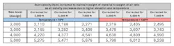
As Table 1 shows, if a system was designed to operate with a 3,000-fpm duct velocity at 70°F at sea-level, that same system operating at an elevation of 5,000 ft would require the duct velocity to increase to 3,282 fpm (about +9%). At 180°F and 5,000 ft elevation, the same system would require the duct velocity to increase to 3,607 fpm (about +20%).
When available, use current site-specific experience for the material being handled when determining minimum duct design velocities. Some high-density dusts (e.g., molybdenum ore dust and some coal dusts) require higher conveying velocities than typical and may warrant laboratory testing or field validation to determine minimum conveying velocities.
For independent laboratory testing of conveying system behavior for your dusts, one option is the Advanced Manufacturing and Bulk Solids Technology Center at Kansas State University. Also, some manufacturers of pneumatic conveying and dust collection systems have in-house testing facilities that can test materials as part of their sales process.
Mismatching inlet and outlet velocities at combining fittings
At wyes and branch entries that combine flows, mismatched inlet and outlet velocities can cause a system that looks good on paper to behave poorly when installed. A practical design goal is to keep inlet and outlet velocities at combining fittings, within about 10% of each other. Because duct is built in whole-inch diameters, treat conveying velocity as a design range (for example, 3,800–4,200 fpm), not a single number. Systems will tend to settle to a common velocity somewhere in the middle of the design range.
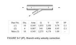
If the outlet velocity of a combining fitting is higher than both inlet velocities, Industrial Ventilation provides a means of determining the extra static pressure required to accelerate the air to this higher velocity. This calculation starts with determining the combined weighted average of the inlet branch Velocity Pressures (VPr) entering the fitting (Industrial Ventilation 31st Ed. Equation 9.19, page 9-24).
{VPr = (Q1/Q3)VP1 + (Q2/Q3)VP2}
The static pressure immediately after the combing fitting is defined as follows (Industrial Ventilation 31st Ed., Equation 9.20, page 9-24):
{SP3 = SP1 – (VP3 – VPr)}
which defines the static pressure needed at Point 3, to account for this increase in air velocity. The final value that I apply for determining the additional pressure required, for adding to standard combining fitting pressure drop is:
VP3 – VPr
Figure 1 shows an example from Industrial Ventilation.
Failing to account for system air leakage
Proper design, particularly for large multi-point collection systems, must account for some system air leakage. Rotary valves present two paths for air leakage; valves will 'pump' air into the dust collector hopper while rotating and will also leak air when stopped under differential pressure. Total leakage is the sum of these two leakage paths.
Ask manufacturers for leakage determinations for their valves at your temperature, including consideration for rotor speed and differential pressure across the valve. If such information is not available, 50–100 cfm per valve is a reasonable placeholder for quality valves, depending on clearances and speed.
Ductwork also leaks. A common allowance for duct leakage is 5–8% of total system flow. The larger the system and the more balancing dampers employed, the greater the leakage. When designing a system, I evaluate and add this leakage air when determining the final air volume for the fan purchase. On a small system, you may be able to ignore duct leakage as long as all duct seams are sealed with metallic peel-and-stick duct tape, but you should never ignore rotary valve leakage.
In Part 3 of this article, I’ll discuss system fan mistakes in high-velocity dust collection systems.
About the Author

Greg Black
Gregory J. Black, P.E. (Mechanical) has extensive experience in the design, application, and maintenance of industrial ventilation and dust collection systems, including applications engineering roles alongside the original patent holders for Venturi-based compressed-air filter cleaning (MikroPul) and with the Air Pollution Equipment Control Division of FLSmidth. For more than two decades he has operated Golden Eagle Technologies, LLC (Golden, Colorado), supplying equipment for granular material processing. Under the service mark, Baghouse Duct Design dot Com, he provides advisement services to plant engineers and engineering firms on industrial ventilation system design, troubleshooting, and retrofits.