Essentials of a successful centralized vacuum cleaning system
A properly designed, installed and maintained centralized vacuum cleaning system can be a major positive asset for housekeeping and employee and property safety, but many systems go unused because they do not function properly. Decades of observation, design, study, installation, maintenance and troubleshooting of centralized vacuum cleaning systems have revealed several essentials for successful operation. A system that complies with these essentials and is properly maintained can operate successfully for decades, and operators will prefer it over other cleaning methods. However, a poorly designed system will not function properly and, if combustible dusts are involved, can become a major explosion, fire or flash fire hazard.
1. Seek a qualified system designer
A centralized vacuum cleaning system should only be designed by a someone who is truly qualified. Experience has shown that equipment vendors or salespersons are not always a good source for proper system design, nor are most engineering and design firms. Few companies or persons have adequate experience to ensure that the design will be successful. Verify that the company or persons you hire have extensive previous successful experience, knowledge of your processes and needs, an understanding of the design requirements and the ability to provide the necessary drawings and specifications. A simple single-line isometric sketch with approximate performance values will not suffice.
2. Establish viable design parameters
It is not feasible to have a successful centralized vacuum cleaning system design unless the system design parameters are established and the consequences understood by all parties involved. Do not mistake this essential requirement for a “wish list” of wants. The parameters should be the true requirements for the system. Often, the parameters are interdependent. The following is a list of some typical parameters (Note that other parameters such as material type can also be important but are beyond the scope of this article.):
Determine the number of simultaneous operators. Typically, the customer will overestimate the number of persons that will use the system simultaneously. This number must be based upon reality, not a desired level, as costs and operational problems can increase exponentially when designing as system for an excessive number of simultaneous operators. Most systems can be designed for either a single operator or two simultaneous operators when the customer rationally evaluates how the system will actually be used and the costs involved.
Determine the hose connection locations. Be generous when planning the locations for inlet valves where the vacuum hose will be connected to the system. Having a high number of locations will not be detrimental to the function of the system if operators are aware of the system performance limitations and the maximum number of simultaneous operators the system can handle. Operators will tend to use the system more when hose connection stations are readily available.
Determine the hose diameter and maximum length. Except in unusual circumstances, the inside hose diameter should be either 1.5 or 2 inches and the maximum hose length should be 25 feet. The 1.5-inch hoses are lighter, easier to handle and usually more flexible and can be better for cleaning around equipment and in limited-space and hard to reach areas. However, the smaller diameter also limits performance, and 1.5-inch hoses and tools should not be used for cleaning up spills or piles of materials.
A 2-inch hose allows for significantly higher performance and can be used for removing spills and larger accumulations of materials. However, the larger diameter also makes the hose heavier, less flexible, and more difficult to manipulate.
Hose length should never exceed 25 feet regardless of diameter. The hose represents up to 50% of the system’s energy losses. Using longer hoses will virtually guarantee poor performance and plugging. The ideal hose length is 15 feet, but it is a rare system that only uses 15-foot lengths.
Determine the maximum conveying distance. Centralized vacuum cleaning systems have a limited effective distance. This is dependent upon the piping/tubing sizes involved, hose diameter and length, and required minimum performance. The number of elbows used in the system can also be a major concern. Combining multiple turns close together almost always results in conveying problems such as plugging. Typically, the maximum distance from the hose to the system’s filter receiver ranges from 300 to 400 feet, though this is not always feasible due to other factors.
Determine where the main equipment will be located. If possible, locate the main equipment in the center of the area to be serviced by the system. This allows maximum performance and coverage. Always allow for maintenance access and functions.
3. Never design for more than two simultaneous operators per line
A major design flaw in many centralized vacuum cleaning systems is the manifolding of the branch lines from a small line (such as 2, 3, 4 or 5 inches) to a larger diameter line. A system designed for 4 simultaneous operators must also consider the more likely scenario of only a single operator. The conveying velocity in the larger line with all operators on the system might be 5,000 fpm or more, while with a single operator that velocity will likely fall below 2,000 fpm. This will definitely lead to material accumulation and eventually reduced performance and plugging.
Trying to use automatic bleed-ins and other methods to compensate will not work. It is not feasible to bleed-in the proper amount of airflow in a branch or main line for every variable in this type of system. This is especially true for systems using positive displacement (PD) vacuum blowers. A centrifugal vacuum blower can use a bleed-in at the blower inlet based upon amperage due to the inherent function of the system, but this type of unit is designed for variable airflows. The only way to ensure adequate airflow, whether one or two operators are on a branch line, is to run the piping/tubing all the way back to the filter receiver. This rarely adds significantly to the costs compared to manifolding into larger lines due to the lower cost of the smaller diameter fittings and tubing/piping.
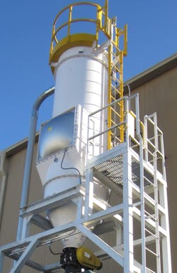
4. Be conservative when selecting the filter receiver
Trying to save a few dollars by selecting a marginal filter receiver (e.g., dust collector or air-material separator) will usually result in major problems. The recommended air-to-filter media ratio is 5:1 or less for bag filters and 1.25:1 or less for cartridge filters. The most common and successful type of filter receiver is a bag filter receiver with pulse-jet filter cleaning, a tangential inlet, an explosion vent (for combustible dusts) and a Class 1 rotary valve for continuous discharge of the collected material. Be sure to optimize the filter receiver design by using a steeply sloped (70-degrees is preferred) hopper section and oversized rotary valve for continuous discharge of the collected material and a tangential inlet section to isolate the incoming material from the filters and reduce grain loading to an acceptable level.
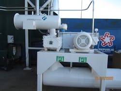
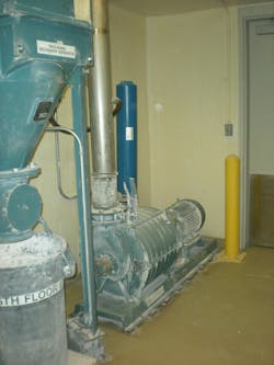
5. Use the correct air mover
Positive displacement (PD) vacuum blowers are the best choice for systems that will only have one operator at a time, while centrifugal exhausters are the best selection for systems that will have two or more simultaneous operators. PD vacuum blowers, typically used in pneumatic conveying, have the advantage of inherently increasing vacuum at roughly the same airflow volume (with a slight reduction) in an effort to unplug temporary material accumulations. A single-operator, centralized vacuum cleaning system with a PD vacuum blower will always be the highest performing type of system.
However, with two or more simultaneous operators (while allowing for just a single operator), the centrifugal exhauster is the best selection. Centrifugal exhausters (like centrifugal fans) inherently provide for variable volume airflow requirements. With proper selection of the impellers (which are multi-stage) the system can maintain the required volume-per-hose. Also, since amperage is directly related to the mass flow through the unit, an automatic bleed-in near the inlet to the unit can be used to ensure that the system never goes into destructive surge conditions.
6. Provide for performance monitoring
The best monitors for system performance are the operators. If they complain about a reduction or lack of performance, then you know there is a problem. The following additional methods are recommended as a minimum level for monitoring system performance:
- Monitor vacuum blower performance: For a centrifugal exhauster, use the drive motor amperage and the differential pressure at the inlet. For a PD unit, use the differential pressure at the inlet. Transmitters to the PLC are recommended for continuous monitoring.
- Use a zero-speed switch for the rotary valve.
- Use a reliable high-level probe for the cone of the filter receiver. Material accumulation inside the unit represents an upset condition. The goal is to have first-in/first-out flow for the collected material.
- Use a pressure differential transmitter to monitor the differential across the filters.
7. Do not use the minimum airflow volumes at the hose or tool inlet
Too often, the airflow volumes used for system design are the minimum required. This is done to minimize overall system costs but doesn’t consider how the system will be used. Scientific experiments have shown that a 1.5-inch i.d. hose will require nearly twice as long to clean the same area with 70 scfm of airflow entering the hose as it will with 85 scfm. This is known as the third-power rule and is based on the air velocity entering the hose. Also, designers often do not consider the energy losses from material loading in the design and will use the value for performance (e.g., the inches mercury vacuum at the blower inlet) related to air only. Experience has shown that the most effective systems use the following design values, which may cost more initially but will minimize problems in the long term:
- 90 to 100 scfm for 1.5-inch i.d. hoses.
- 180 to 200 scfm for 2-inch i.d. hoses.
- The vacuum at the air mover (either type) should be a minimum of 11.0 inches mercury but preferably 12 inches mercury. This allows for material loading and other unknown factors.
8. Additional items to consider
While this article cannot discuss all system design essentials at length, also consider the following additional items:
- Predetermine the best routing for all piping/tubing runs and minimize elbows.
- Use only commercially available tubing, piping and fittings because they have the lowest air-friction values.
- Consider your material characteristics. If your material is light, non-abrasive and free-flowing, lower conveying velocities may be feasible. However, if your material is heavy, adhesive, cohesive or consists of larger particles, higher velocities should be used.
- Be sure to comply with any combustible dust requirements.
- All systems should be properly bonded and grounded. All hoses and tools should be properly bonded and grounded and should be static dissipative.
- Use the commercially available tapered inlet and spring-operated, self-closing hose connection fittings.
- Never use 90-degree tee connections.
- Use multi-bolt compression clamp connections (the same type used for pneumatic transfer systems). Keep the fittings and piping/tubing runs straight to minimize accumulation.
9. Understand that plugs will occur
Finally, no centralized vacuum cleaning system design can completely eliminate plugging in the piping/tubing. Anything that can fit into the hose — such as plastic liners, tools, pencils, pens, welding rods, splinters, paper sheets, bolts, etc. — could enter the system and plug the line. Installing small bars across the inlet can help to minimize plugging but will not entirely eliminate the problem. Even the very best system can plug, but a well-designed system plugs only under upset conditions and not during normal operation.
Jack Osborn ([email protected]) is senior project engineer at Airdusco Engineering and Design Services and a member of Processing’s editorial advisory board. He has more than 46 years of experience in dust collection systems, centralized vacuum cleaning systems, pneumatic conveying systems and all types of bulk handling systems and is a participating member of all six NFPA combustible dust committees.
Airdusco Engineering and Design Services
About the Author

Jack Osborn
Senior Project Engineer
Jack Osborn is senior project engineer at Airdusco EDS and a member of Processing’s editorial advisory board. He has more than 50 years of experience in dust collection systems, centralized vacuum cleaning systems, pneumatic conveying systems, and all types of bulk handling systems. He has either designed or evaluated (e.g., engineering studies/audits, performance testing, etc.) more than 2,000 dust collection systems during his career and is a participating member of all six NFPA combustible dust committees.