Five essentials for optimizing hammermill operations
The hammermill is one of the most common industrial size reduction devices. As with most types of process equipment, the hammermill’s name describes its function: a number of “hammers” are mounted to a shaft that rotates at high speed within a chamber to “mill” bulk solid material to a desired particle size range. Screens inside the mill allow properly sized particles to exit the mill while keeping oversized particles in the milling chamber. Many operational factors are essential in determining a hammermill’s ability to achieve the desired process goals. This article will discuss five essential operational requirements for optimal hammermilling.
It is important to emphasize that the optimization methods presented here are not based on theory or academics but rather on direct experience and have been utilized and proven in actual application.
1. Control and monitor the material feed rate to the mill
Hammermill performance cannot be optimized without having full control of the material feed rate to the mill. This is necessary to maintain a consistency. The hammermill feeding device is typically supplied by the mill supplier and is most commonly a pocket rotary feeder or rotary airlock valve.
However, these devices are volumetric. The mass (or gravimetric) feed rate to the mill depends on material characteristics, including flowability, consistency of bulk density and particle size. Additionally, if the material supply above the pocket feeder or rotary valve is not a consistent “flood-feed,” then the pocket-fill rate can deviate significantly, resulting in a wide fluctuation in mass feed rate to the mill. The resulting inconsistent feed rate to the mill creates unwanted deviations in the milling process. This is especially significant when a mill is used with varying materials and can result in wide deviations in performance.
The optimal material feeding method for a mill provides a reliable and consistent mass feed rate to the mill inlet. This consists of a gravimetric feeding device such as a weight-loss feeder or weigh-belt feeder feeding a custom-designed feed hopper to the rotary airlock valve or rotary pocket feeder. The gravimetric feeding device provides a weigh-based consistent rate, and the feed hopper ensures a flood-feed to the metering device for the mill.
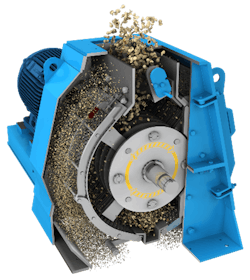
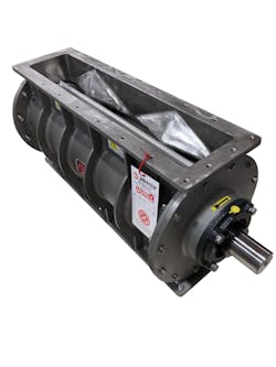
Controlling the feed rate and ensuring mass-flow characteristics to the direct mill feeding device is critical to success. Most systems use pocket rotary feeders and custom rotary valves. The pocket rotary feeder is designed for this application and provides a consistent, non-pulsing direct rate to the mill inlet and allows a controlled intake of airflow on both sides of the rotor, as shown in Figure 4.
A rotary valve, with a large single pocket per vane or row, does not provide a non-pulsing flow, especially at lower rpms. At higher rpms, a rotary valve will approximate a continuous feed to the mill, but air intake is not an integral part of the valve, so it requires a separate air intake on both sides. The rotary valve can meet class 1 construction for isolation, which is a critical factor in mill selection should an explosion occur inside the mill. The rotary pocket feeder does not provide class 1 clearances and cannot be used as an isolation device for combustible dust compliance.
Controls for this part of the process include a variable frequency drive (VFD) for the pocket feeder/rotary valve, master/slave (or similar) operation of the weigh-feeder with the pocket feeder/rotary valve, and additional monitoring to ensure that the feed hopper level is maintained.
2. Ensure adequate levels of induced airflow through the mill
With the exception of some rare applications, hammermills are air-assisted devices. Proper operation requires induced airflow through the mill body, both internal and external to the screens. The air-assist or induced airflow through the mill has the following functions:
Controlling product temperature during milling. Milling operations generate heat. This heat must be transferred to the air-assist airflow to prevent product degradation, screen blinding, or even a fire or explosion. The temperature must be kept below a maximum level and preferably maintained within a small preset range. Cooling air is often used to assist with this process during higher-temperature seasons.
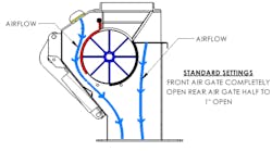
Optimizing hammer performance. Too little or too much airflow can reduce hammer performance. The incoming airflow, combined with the material feed, follows a predetermined pathway within the mill to a baffle (or baffles). The purpose is to use turbulence in the airflow to optimize material impact with the hammers and material-to-material attrition.
Pulling properly sized material through the screens. The induced airflow (with some help from the rotating hammers) provides the differential pressure and mass-flow-media required to pull properly sized material through the screens. Again, too little airflow will result in over-milling (reducing the particle size below the desired level), while too much airflow will extrude larger-than-desired material through the holes of the screen. Either too little or too much airflow can lead to premature blinding of the screens.
Minimizing buildup. Too little airflow can lead to excessive material buildup inside the mill.
Providing conveying airflow. The induced airflow also provides the majority of the airflow required to convey the milled material to the filter receiver.
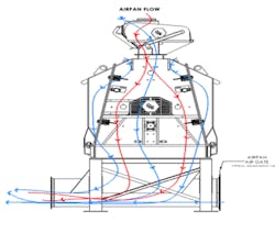
The induced (vacuum) airflow through the mill comes from two sources. First, air flows through the rotary pocket feeder (or below the feed from the feeder) into the main body and internal to the screens. This comprises approximately 80% to 90% of the airflow through the mill.
The second source is from slots in the mill body, which are typically ¼ inch or less and are opened to provide the remaining 10% to 20% of the air-assist for milling functions. This airflow tends to keep the internal walls of the mill cleaner for longer and is used in the pneumatic transfer process.
Additional airflow is usually required when pneumatically transferring the milled material to a filter receiver. This is the most common method of handling the milled material, but it is also feasible to discharge the milled material directly into a large bin with a bin vent sized for the induced airflow (thus, the mill discharges directly into this hopper equipped with filtration). The amount of additional airflow provided for pneumatic transfer is in the range of 20% of the overall airflow (the airflow through the mill and the amount added for conveying). Conveying velocities should be kept at a minimum of 5,000 fpm when friability is not a factor. Higher velocities may be needed for some materials. The conveying distance and routing must be kept at a minimum, with as few turns as is reasonable. Some materials are highly friable and may require semi-dense phase vacuum conveying or a similar method.
Directly discharging material from a mill into a small plenum above a screw conveyor, even when equipped with adequate filtration, is not recommended. Typically, the air velocities inside the plenum (extension above the screw conveyor) are still adequate to carry dust to the filter unit instead of allowing the material to remain as part of the screw conveyor feed. This results in overloading of the filtration system. This also represents a significant combustible dust hazard that must be considered when handling combustible milled products.
The controls for this portion of the milling operations can vary, but proper monitoring and control of these operations is critical. Typical parameters include the temperature of the airflow into and out of the mill, the differential pressure into and out of the mill, the mill bearing temperature and vibrations, the amperage of the rotary feeder (with VFD), amperage of the mill drive motor, and the amperage of the fan package drive motor used to provide the induced airflow through the mill and for pneumatic transfer.
Materials that are temperature sensitive may require cooled and humidity-controlled airflow to prevent screen blinding and material degradation.
3. Ensure proper screen sizing
Proper screen sizing is critical to hammermill performance. Have a supplier test the material to determine what screen size will be best to produce the desired material results. Testing is also beneficial for determining the proper induced airflows, operating temperatures, and more. For existing operations, experimentation may be necessary to determine the optimal screen sizing.
4. Adequately filter the airflow through the mill and for pneumatic transfer
Improperly sized and designed filter receivers result in poor and inconsistent mill performance and poor product quality. In addition, the increased maintenance often results in unacceptable operational costs and machine downtime.
Do not consider the filtration device as a simple dust collector. True dust collectors are designed to operate at grain loads far below the loads that come from a milling process. Filter receivers are designed for high material loads and have cylindrical filter units with tangential inlet sections designed to remove, mainly by cyclonic flow, the vast majority of the milled material before it reaches the filters. The cylindrical shape is also better suited for collected material discharge and for handling food products with stringent cleaning requirements.
The filter receiver is often one of the more costly components of a hammermill system, so there may be a desire to cut costs here. This is usually a major mistake. The amount of filter area in relation to the volume of airflow is highly critical to successful milling. There is no such thing as too much filter area, but air-to-filter media ratios should be no more than 5:1 for bag filters and 1.5:1 for cartridge filters. Some materials will require even lower ratios due to their material characteristics, such as cohesiveness, adhesiveness, particle size, and bulk density. The air-to-filter media ratios are also the air velocities through the filter — an air-to-filter media ratio of 5:1 is an air velocity of 5 fpm.
Also, the rising air velocity in the filter unit (the velocity between the filters) must be kept as low as is reasonably possible (due to typical physical limitations). This velocity is based on the material characteristics and testing. Velocities must usually be below 200 fpm and may need to be significantly lower for some materials. Excessive velocities will cause material to remain airborne around the filters and lead to premature filter blinding and problems with the collected material discharge system.
Controls include the differential pressure across the filters, the differential pressure to the fan inlet, monitoring of the material level inside the unit (do not use the filter receiver as a storage unit), and performance of the collected material discharge system.
5. Ensure proper fan selection
Proper fan selection, along with proper filter receiver selection, represent the typical problem with many hammermill operations. The fan must be sized for the full range of milling system requirements. The fan must be located on the clean side of the filter receiver. Always get a fan performance curve from the vendor before purchase and ensure that the curve fits the system requirements. Do not use a VFD for operation, as extensive experience shows that this will lead to future operational problems. However, do include an inlet radial damper (manual or automatic) which can be used to vary the performance curve without wasting energy.
Jack Osborn ([email protected]) is senior project engineer at Airdusco Engineering and Design Services and a member of Processing’s editorial advisory board. He has more than 46 years of experience in dust collection systems, centralized vacuum cleaning systems, pneumatic conveying systems and all types of bulk handling systems and is a participating member of all six NFPA combustible dust committees (61, 484, 652, 654, 664, and Correlating).
Airdusco Engineering and Design Services
About the Author

Jack Osborn
Senior Project Engineer
Jack Osborn is senior project engineer at Airdusco EDS and a member of Processing’s editorial advisory board. He has more than 50 years of experience in dust collection systems, centralized vacuum cleaning systems, pneumatic conveying systems, and all types of bulk handling systems. He has either designed or evaluated (e.g., engineering studies/audits, performance testing, etc.) more than 2,000 dust collection systems during his career and is a participating member of all six NFPA combustible dust committees.