Counteracting external influences on feeding accuracy
Loss-in-weight (LIW) feeder performance is affected by a number of influences, both internal and external to the feeder and feeder process. Understanding the significance of these influences is critical for achieving optimal performance. This article will describe some strategies to help ensure accurate weighing with your LIW feeder.
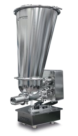
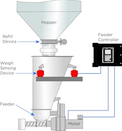
A LIW feeder is a gravimetric device that directly measures a material’s weight to achieve and maintain a predetermined feed rate, which is measured in units of weight per time (such as pounds or kilograms per hour). The LIW feeder, as shown in Figure 1, generally consists of a hopper, a refill device, a weight-sensing device (digital or analog), a feeder (for example a screw feeder powered by a variable-speed motor), and a controller.
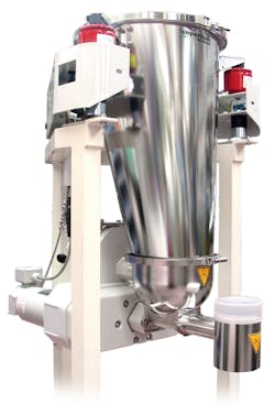
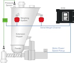
Before use, an operator programs the controller to discharge material at a predetermined feed rate (or setpoint). The feeder can either be mounted on a platform scale, as shown in Figure 2, or suspended on load cells, as shown in Figure 3. If the measurement taken by the weighing device is inaccurate or influenced by outside forces, the resulting mass flow from the feeder may be inaccurate or inconsistent. This inaccuracy not only sends an incorrect amount of material to the process below but can also result in increased material costs due to the deviation from the mass flow setpoint.
LIW feeders are used in both batch dispensing and continuous feeding applications. As manufacturers look to automate their processes with LIW feeding, they are also looking to optimize overall ingredient costs. Slight changes in the mass flow accuracy of a feeder or multiple feeders can make a significant difference in both product quality and raw ingredient costs. A LIW feeder can be especially sensitive to ambient influences because it must precisely and continually measure very small differences in the weight of a relatively large load, which includes the feeding equipment itself.
Ambient influences such as environmental factors and improper installation and maintenance can be crucial to the weighing operation. These influences include vibrations that are transmitted to the weighing system from nearby machinery, insufficiently flexible inlet/outlet connections, random physical shocks (such as bumping the feeder while in operation) and other mechanical disturbances, as well as pressure variations within the system and at the process connections. Even air drafts and currents in the processing zone, if excessive, could affect weighing performance. The following describes three of the main influences and how to counteract them.
Counteracting ambient vibrations
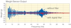
Vibration from other pieces of machinery can cause incorrect readings by the weighing device. To help compensate for any potential vibrations, modern weighing technology and controllers use sophisticated filtering algorithms to discriminate between the load to be measured and transient forces imposed by vibration. When applied to the process data, the algorithm helps the controller identify and extract frequency components characteristic of in-plant vibration, as shown in Figure 4. Even with such filtering algorithms, it is essential to further ensure that the feeder has a stable mounting by using the recommended shock mounts and platform acceleration measurements as recommended by the feeder supplier. In addition, when dealing with very low feed rate applications, it is also important to eliminate strong air currents near the feeder, as the currents can move across the scale and influence the weight readings.
Isolating the feeder from other processes
Since the LIW feeder’s operation depends on accurate weight measurements of the material in the hopper, it is imperative that the feeder and weighing devices are completely isolated from the upstream and downstream processes to avoid influencing the overall weight signal. In the case of a continuous process, the upstream process may include a pneumatic receiver or a large hopper or intermediate bulk container (IBC) — both with a modulating valve. If this receiver or hopper is directly coupled to the feeder, the scale interprets the overall weight as being much higher. Therefore, it is essential to isolate the feeder with flexible connections to both upstream and downstream equipment, allowing for adequate space for maintenance.
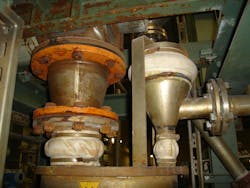
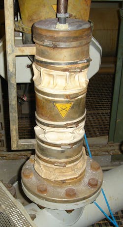
Flexible bellows connectors are the most common connection type. Bellows connectors are typically constructed of a flexible elastomer, such as silicone. If these connections are too tight, they will exert excessive tensile force on the feeder below, which can cause the feeder controller to give an incorrect weight signal. Conversely, if the bellows are being sucked inward due to influence of pressure, these forces will also cause deviations in the weight signal. Figure 5 illustrates bellows designs that are too tight and too loose.
It is essential that the process connection isolates the feeder from any noise or force that may influence the feeder and scale performance. These issues often result after shutdown or maintenance, where the flexible connections have been re-installed improperly. If your feeder is experiencing performance issues after a maintenance program, the first troubleshooting step should be to examine the system’s flexible connections.
Compensating for pressure and vacuum shifts
If a LIW feeder discharges material to a non-ambient-pressure environment, such as a pressurized conveying line, a pressure pulse (air leaking from the downstream system through the feeder’s discharge tube to the weight sensing device) can cause a feed rate error. Such a pressure pulse exerts a vertical force on the weight sensing device opposite to the hopper’s downward force. In effect, this force slightly lifts the load, so the controller reads a lower weight than it should and decreases output to compensate for what it interprets as overfeeding.
In addition, discharge pressure problems may be caused by extruder back pressure or vacuum, which are caused by changes in the downstream process. This could be back pressure in a mixer or extruder or vacuum influences by a micronization or milling system, for example. To mitigate pressure fluctuations on the outlet, the cap may be isolated from the feeder by a flexible bellows rigidly mounted to an outside structure, such as a supporting frame.
At the same time, a feeder’s refill cycle increases air pressure in the hopper due to the sudden inflow of material. Any positive air pressure acts equally in all directions and so also pushes up on the hopper lid and the refill valve. Because the force in the inlet area is not applied to the hopper lid but to the refill valve above, pressure forces inside the hopper are not balanced. Due to the inlet opening, forces acting upon the lid are lower than those acting in the opposite direction upon the hopper floor. These higher forces result in an increase in the weight signal. The LIW controller would interpret the increased weight signal to mean that mass flow is slowing and react by erroneously increasing the feeder output and creating a mass flow error.
One of the most common sources of pressure fluctuations in LIW feeders is the presence of a clogged or blocked dust collection vent filter. Sometimes fluctuations can occur when the dust collection system or nitrogen blanket is connected across many feeders — when any of the feeders refill, the others experience pressure pulses transferred via the connected air lines.
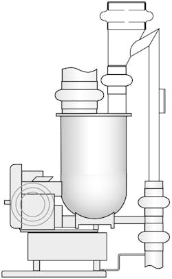
Traditionally, these troublesome pressure fluctuations have been compensated for by mechanical means, as shown in Figure 6. However, factors such as mechanical tolerances, the alignment and age of the flexible bellows, and more can impact the mechanical pressure compensation and prevent the pressure from fully compensating for the forces generated by changing pressures, often making this costly solution deficient.
Today, electronic pressure compensation is an effective but simple alternative to mechanical pressure compensation. Electronic pressure compensation can significantly improve the feeding accuracy of gravimetric feeders in closed systems and can be less expensive than traditional solutions. In addition, the electronic solution is more reliable, is maintenance free, and is easy to retrofit onto existing systems.
As shown in Figure 7, electronic pressure compensation uses a high-precision pressure sensor mounted on the hopper lid and/or the outlet tube to constantly measure the pressure. The signal from the sensor is transmitted via sensor board to the feeder control system, where it is used to dynamically compensate for pressure fluctuations and prevent weighing errors. The pressure sensor can be installed on the feeder hopper or outlet or both. It is also possible to use electronic pressure compensation for the hopper, while using traditional mechanical pressure compensation on the outlet.
In summary, it is important to remember that environmental influences such as vibrations, process connections and pressure fluctuations can have a direct effect on the accuracy of a LIW feeder. By implementing some of the optimization strategies outlined in this article, higher performance standards for continuous LIW feeding can be achieved, as well as an overall increase in process profitability and quality.
Sharon Nowak is global business development manager for food and pharmaceutical ingredients at Coperion K-Tron.
Coperion K-Tron
About the Author

Sharon Nowak
Sharon Nowak is global business development manager for food and pharmaceutical ingredients at Coperion K-Tron.
