How feeder design impacts silo discharge
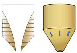
Reliable bulk solids material flow from a bin or silo requires that the silo hopper is designed to create the correct flow pattern (funnel flow or mass flow) during discharge. In funnel flow, material above the hopper outlet moves during discharge while material along the hopper walls remains stationary or stagnant (Figure 1, left). In mass flow, all the material moves whenever any is withdrawn (Figure 1, right). Most silos handling powders require a mass-flow pattern. If the silo flows in a funnel-flow pattern, the material will be susceptible to flow problems such as ratholing, flushing and segregation.
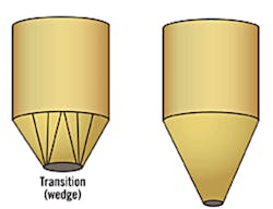
A feeder must work in unison with the silo to ensure reliable flow. Screw, belt and rotary valve feeders are commonly used to maintain mass flow. Screw and belt feeders are typically used to control discharge from slotted or wedge-type hoppers (Figure 2, left) but can also be used to control discharge from conical hoppers (Figure 2, right). Rotary valve feeders are typically used for circular or square hopper outlets.
Screw feeders are a good choice for handling dusty or toxic materials because they are enclosed devices. A screw feeder is also compact and will minimize height problems but may cause particle breakage with fragile materials.
Volumetric screw feeders
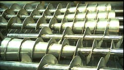
Volumetric screw feeders are composed of wound flights of stainless or carbon steel. They have a particular diameter and pitch (distance between flights) and require a shaft designed to withstand deflection. The key to proper screw feeder design is that the flights must increase in capacity in the discharge direction in order to withdraw material from above in mass flow.
A volumetric screw feeder discharges some volume of material per unit time. The feeder relies on screw speed to adjust the flow rate and can achieve a feedrate accuracy of 2%. If designed properly, a volumetric screw feeder will maintain a mass-flow pattern.
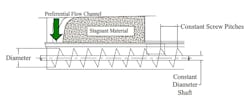
A feeder with a constant-pitch screw will withdraw material preferentially from the back, as shown in Figure 3. If such a feeder is mounted below a mass-flow hopper, this preferential flow channel will convert the hopper’s mass flow pattern to funnel flow, which will likely cause a stable rathole to form.
An alternative to a constant-pitch screw is to use an increasing-pitch screw that provides the increase in capacity in the discharge direction required to maintain mass flow. A slot length of 3 times the screw diameter is recommended to maintain pitch tolerance. If any flight pitch decreases, material will back up in the hopper.
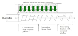
A conical section of shaft with ½-pitch flights can also be used to maintain mass flow, because the capacity increases in the discharge direction. This approach also requires a recommended slot length of 3 times the screw diameter to maintain pitch tolerance. Typically, a mass-flow screw uses a combination of the two, as shown in Figure 4, with a section of conical shaft with ½-pitch flights connected to a section of increasing pitches. In addition, a conveying section is added to the screw to provide discharge to the downstream process.
As a rule of thumb, the screw speed should be between 4 and 40 rpm. A speed slower than 4 rpm would require a large, expensive speed reducer, and at speeds faster than 40 rpm, the screw becomes inefficient, and the screw flights do not fill properly.
While V-shaped troughs are common, material in a screw can only flow vertically and not along the walls of a V-shaped trough. As a result, U-shaped troughs are recommended.
A shroud is located just beyond the hopper outlet. This shroud turns the material flowing in the U-shaped trough into circular plug. The shroud is about one screw diameter in length and limits the screw capacity, allowing better flow control through the screw. Hanger bearings are destructive because they block material flow and cause material to back up into the hopper.
Finally, torque and horsepower calculations are based on the screw’s running torque, but when filling the screw from empty, an initial fill pressure is created, requiring a startup torque on the order of 2.5 times the running torque. This can be avoided by starting the screw at a slow speed during filling to eliminate the initial fill pressure, which allows the screw to operate at running torque.
Belt feeders
A belt feeder uses a moving belt supported by idlers and is very useful when handling sticky or fibrous materials or for controlling flow from large, slotted hopper outlets when handling cohesive materials. A belt feeder is not recommended when handling fine powders or fluidizable materials.
As with a mass-flow screw, the belt capacity must increase in the discharge direction and the material must be deposited uniformly onto the belt along the entire length of the hopper outlet. A typical belt feeder is directly attached to the hopper and uses some sort of adjustable gate to control flow and the height of the pile on the belt.
There is no way to ensure an increase in capacity on the belt. The material will withdraw preferentially from the front or back, converting the mass-flow pattern from the hopper to funnel flow and likely creating a stable rathole. One way to establish a capacity increase in the discharge direction is to modify the hopper outlet to increase in elevation view from back to front. A second way to accomplish this is to widen the hopper outlet along the length in plan view.
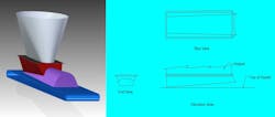
Using a belt feeder interface that increases in both elevation and plan view, as shown in Figure 5, is recommended. The 45-degree slanted nose at the front of the interface relieves stress on the interface and prevents material from building up on the discharge wall of the hopper.
Rotary valve feeders
Rotary valve feeders are most frequently used with circular or square hopper outlets. Specialized designs allow for feeding over a slotted outlet by either coupling multiple feeders together or by using an extended-length design.
A rotary valve feeder consists of a housing with a flanged inlet and outlet. Within the housing, a series of pockets or vanes rotate around a horizontal shaft. Material discharge is determined by the volume of the pockets and the speed of rotation.
In many applications, a rotary valve feeder will serve at least two functions: metering the material discharge and sealing against a pressure gradient from the downstream system, such as a pneumatic conveying line. Many vendors refer to feeders with this dual capability as rotary airlocks.
Many nuanced changes in valve performance can be introduced by altering the number and style of valve pockets as well as the material entry location into the valve (straight drop-through or side entry). These design features are influenced by both the material flow characteristics and the performance requirements of the device.
For hopper discharge, the pockets of rotary valve feeders tend to fill prior to completing their travel across the cross-section of the hopper outlet. As a result, a preferential flow channel often develops, with material feeding from only one side of the outlet, as shown in Figure 6 on the left. This can convert mass flow to funnel flow, often leading to a preferential flow channel that may induce eccentric loading in a silo.
A second flow problem frequently encountered when using rotary valves is that the empty pockets contain a volume of displaced air (Figure 6, left). Depending on the material’s permeability and the valve’s rotation speed, this can lead to inefficient filling of the valve and further challenges to reliable discharge.
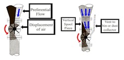
One approach to address preferential flow is to add a vertical spool piece above the valve inlet and the bin outlet, as shown in Figure 6 on the right. The required height of this piece depends on the material’s properties, but a height of up to 2 times the valve diameter is often sufficient. Such a vertical section allows for a preferential flow channel to expand upwards, enabling material to discharge across the hopper outlet’s entire cross section. Many valves also now offer a body vent (Figure 6, right) that allows the displaced air to escape from the empty pockets and be captured by a dust collection system.
Gravimetric feeding
Each of the feeding devices already described (screw feeders, belt feeders and rotary valves) allows for volumetric control of the discharge rate. For many systems, this level of control is adequate to reliably meter material from the bin. But if the material’s bulk density varies, the feedrate can deviate from the desired output. The more homogeneous the material is when discharging from the hopper, the more constant the discharge rate will be. In a mass-flow bin, material density variations at the outlet are minimized by exposing material to a fairly consistent stress history. Fluctuations in material density can still arise from deviation or segregation in the material. Also, even in mass flow, with a volumetric feeder, initial fill conditions and final discharge during cleanout may result in higher or lower density values at the same operating output.
Gravimetric feeding provides a greater level of control by incorporating a weigh system into the feeder’s operation. The specific discharge device used often coincides with the volumetric devices already discussed, but the feeder senses the weight of material dispensed on a time basis and uses that data to modulate the device’s output based on a predetermined setpoint.
Gravimetric feeders operate on either a loss-in-weight (LIW) or gain-in-weight (GIW) basis. A LIW feeder controls the discharge rate based on the weight of material exiting the system. A LIW feeder, as shown in Figure 7, has a refill hopper with a means of feeding or isolation from the upstream material, a feed hopper and a discharge device. The weight of the feed hopper, material and discharge device is continuously measured, and the weight loss over time is used to monitor the discharge rate. This information is then used to adjust the discharge device’s output to achieve the desired rate.
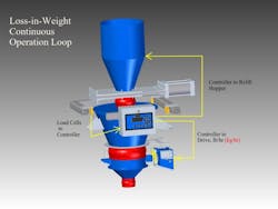
During continuous feeder operation, the feed hopper is filled from the supply hopper (or device) and then stopped once full. The total weight now serves as a starting point, and the output on the discharge device is matched to a certain weight change over time. This provides a precise level of control on the discharge rate to a 0.5% feedrate accuracy.
At some point, the material level will be depleted, and the feed hopper will need to be refilled. Weighing is impossible during refill, so the feeder’s output is held constant, leading to volumetric output control. As a result, a very rapid refill time is required to minimize the error introduced during the refill process.
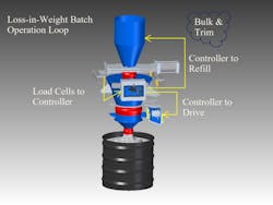
For a batch process, a LIW feeder operates in a bulk-and-trim mode, as shown in Figure 8. A certain amount of material is selected (for instance, the amount required to fill a drum), and the feeder discharges at maximum feedrate until it nears the selected amount. Then the feeder switches to trim mode, where the feedrate slows to provide the final amount of material with greater control. For batch operations, the required feedrate and accuracy influence LIW feeder selection, which will be a function of the feeder’s turn-down ratio.
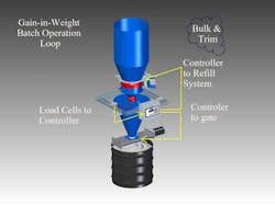
A GIW feeder, as shown in Figure 9, operates on a similar principle but monitors the increase (or gain) of material over time. GIW feeders do not provide continuous feed and are used for metering materials into batch operations. A refill hopper and feeder discharges material into a feed hopper with an outlet gate. The feeder hopper and material are weighed, and the weight increase from empty is used to monitor the amount of material fed. A similar bulk-and-trim mode exists, where material is fed at a very high rate until the total weight approaches the setpoint, and then the feeder switches to trim mode and trickle feeds the remaining material for accuracy. Once all the material has been fed, the gate on the feed hopper opens, depositing the batch of material to its destination, such as a bag, tote or drum.
This article has been just a brief sampling of the devices currently available to control the rate of discharge from a storage vessel. For applications where the required level of accuracy is 5% or less, a volumetric feeding device will likely be sufficient. Where greater control of the discharge rate is required, a gravimetric feeding device will be needed.
Regardless of the feeding device chosen, if the storage vessel has not been designed to account for the material’s flow characteristics and the application’s specific performance requirements, the feeding device will not function appropriately. Material flow from a bin is inextricably linked to how the feeder extracts material from the outlet, and successful material handling requires the hopper and feeder to operate in harmony with each other.
Joseph Marinelli is a bulk materials handling expert and founder of Solids Handling Technologies, Inc. (803-802-5527, [email protected]). He has been active in testing bulk solids and consulting on material handling systems since 1972 and has taught hundreds of engineering seminars. He holds a BS in mechanical engineering from Northeastern University in Boston, Massachusetts
Scott Miller has been a consultant with Solids Handling Technologies since 2016. He has a BS in mechanical engineering from Geneva College in Beaver Falls, Pennsylvania.
Solids Handling Technologies, Inc.
About the Author

Joseph Marinelli
Joseph Marinelli is a bulk materials handling expert and founder of Solids Handling Technologies, Inc. (803-802-5527, [email protected]). He has been active in testing bulk solids and consulting on material handling systems since 1972 and has taught hundreds of engineering seminars. He holds a BS in mechanical engineering from Northeastern University in Boston, Massachusetts.