The makeup of liquid and gas process streams are critical parameters that are monitored in a wide range of industrial plants including chemical production, refineries, food production and steam generation facilities. Changes in the fluid composition and/or properties can affect the quality of products, change the stoichiometry or rate of a reaction, or result in corrosion and deposition in process equipment. Unfortunately, many plants do not have properly designed and operated sampling and monitoring systems to accurately determine the process fluid composition and properties. As a result, operating decisions are often based on data that can have large sampling errors. These errors, as well as data inconsistencies and concentration swings in the analytical results, become commonplace and are often ignored by plant personnel, preventing the timely identification of actual process chemistry excursions. This article outlines the principles that must be considered when designing and operating sampling systems for process streams including water-based solutions, steam and hydrocarbon liquids and gases.
Sampling system design
Proper design of the sampling systems is critical in order to produce samples and analytical results that are representative of the sampled stream [1-6]. A meticulously performed analysis is of little value if a bad sample is used. As shown in Table 1, there are many potential causes of sampling errors, some of which can cause analysis results to be several orders of magnitude higher or lower than the actual conditions in the process stream.
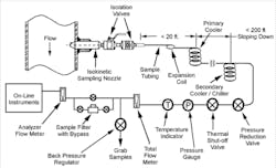
The components of a sampling system can vary depending upon the analytical requirements, process conditions and process fluid properties, but a typical well-designed sampling system (Figure 1) consists of an isokinetic sampling nozzle (discussed below), isolation valves, sample tubing, primary sample cooler (and secondary cooler for steam and high-temperature liquid and gas samples), pressure-reduction and total-flow-regulation valves, a thermal-shutoff valve (for process temperatures above 100ºF), back-pressure regulator (when on-line instrumentation is used) and sample drains or return to process.
When to use isokinetic sampling
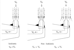
Isokinetic sampling is the extraction of a representative portion of the process stream without altering the physical and chemical properties of the sample. In isokinetic sampling, all phases (solid oxides and precipitates, liquid droplets and vapor) of the sampled fluid enter the sampling nozzle with the same velocity vector (meaning the same velocity and direction of flow). The main reason isokinetic sampling is necessary is that sampled streams are often a two-phase fluid (gas-liquid, gas-solid, liquid-solid) and the second phase typically has a different chemistry composition than the bulk fluid. In addition, the second phase (droplets or particles) typically has a different density and inertia compared to the primary phase (gas or liquid) and therefore would not be proportionally represented in a sample that was not withdrawn isokinetically (Figure 2).
In cases where the process fluid is a uniformly mixed, single phase liquid or gas, isokinetic sampling is not necessary, however, the preferred method is to use a sampling nozzle to extract fluid from a location away from the process pipe wall. A sample point, such as a surface tap, that extracts a sample that includes the boundary layer fluid is not recommended. Often, the fluid within the boundary layer at the process pipe wall is not representative of the bulk fluid.
Sampling nozzle design
The design of the sampling nozzle (Figure 3) is a critical part of the sampling system and should be performed prior to the selection of the other sampling system components. Proper sampling nozzle design must consider the effects of flow- and vibration-induced forces on the sampling nozzle, as well as the design pressure and temperature. The sampling nozzle is normally a solid probe with a short tapered vertical tip (Figure 1) or a short-radius tube to extract the sample away from the nozzle body to reduce flow effects. An alternative is a tube or pipe cut at a 45-degree angle, but that flat surfaces around the orifice can affect the local flow and result in a non-representative sample when sampling two phase fluids.
In the past, multi-port sampling nozzles were used in an effort to simultaneously sample from several location across the diameter of the process pipe. The multi-port sampling nozzle in its most basic form consisted of a piece of pipe with multiple holes in it. That design operates non-isokinetically, is prone to plugging and is susceptible to failure due to vibration, therefore it is no longer recommended.
Transport of samples
Almost any fluid will leave or pick up some residue, both while flowing through a tube and being stored in a container. As a result, any chemical analysis will become biased due to the loss or gain of contaminants. Several factors contribute to deposition on the tubing wall, including crystallization resulting from solubility changes, settling due to gravity and hydrodynamic forces, and electrostatic attraction of charged particles. Whenever the sample is not in equilibrium with the fluid-touched surfaces, the sample composition will be changed from its original state. In general, the time for sample tubing to reach equilibrium decreases with smaller tubing (due to decreased surface area) and increased sample velocity. Even when a sufficient sample velocity is maintained, reaching equilibrium can take from minutes to hours depending upon the purity of the fluid being sampled. It is for this reason that it is often recommended that sample streams should flow continuously rather than be periodically started and stopped.
The total length of sample tubing should be as short as possible and sized so that for the required sampling rate, the sample flow velocity is maintained at approximately the process flow rate. Lengthy sample lines or low sample flowrates can result in unacceptable time lags between sample extraction and analysis. A liquid sample flowing at 1 foot per second through 200 feet of tubing will take more than three minutes to reach the analyzers. Low sample residence time in the tubing is also preferred to limit chemical reactions and sorption on oxides.
Additional considerations
When designing a sampling system such as that shown in Figure 1, follow these recommended practices for each of the components discussed below:
- Sampling system materials. Metal oxide deposits can act as ion exchange media and adsorb or release impurities during changes in the flow conditions. For this reason, all wetted components of the sampling system should be made from a material with low oxide formation under process conditions. In many systems, Type 316 stainless steel or a higher alloy are recommended, and carbon and low-alloy steels should be avoided.
- Installation location for the sampling nozzle. The preferred location is in long sections of pipe, away from all flow disturbances (such as bends, valves, and so on). It is recommended that the sampling nozzle be located where the ratio of its distance from an upstream disturbance to downstream disturbance is about 9:1. If the sampling nozzle is installed in a long horizontal section, it should be on the top of the pipe between the 10 o’clock and 2 o’clock positions to allow full drainage of the sampling system during outages.
- Isolation valves. These valves should be rated for the application temperature and pressure, and provide a minimum change of cross-section between the inside diameter of the sampling nozzle and the orifice of the valve.
- Sample tubing. For steam and gas processes, the length of tubing should be as short as possible (not longer than 20 feet for steam systems) to minimize the pressure drop and reduce the possibility of impurity deposition in the sample tubing. The inside diameter of the sample tubing should be close to the inside diameter size of the sampling nozzle, to minimize changes in cross-sectional area, resulting in velocity changes. The sample line should include a series of bends or a coil before the first point of fixation to allow for any movement or expansion of the process pipe. Sharp radius bends should be avoided. The tubing should be downward sloping along the entire length to eliminate any sections where liquid could accumulate during outages.
- Primary and secondary sample coolers. The coolers should be sized to ensure adequate cooling capacity, with allowances for reduced heat transfer due to scale buildup. The cooler tubing should be made from material compatible with the process fluid and the cooling medium.
- Pressure-reduction valve. In medium to high pressure systems, this valve is used to reduce pressure and control the flow of a sample to protect on-line instruments and plant personnel from excessive pressure.
- Thermal shut-off valve. In elevated temperature systems, this valve protects personnel and downstream components by automatically interrupting sample flow when the sample temperature reaches a preset limit, in the event of an insufficient amount or loss of cooling water or a fouled sample cooler.
- Pressure and temperature gages and flow indicator. These devices provide the operator with verification that the system is working properly.
- Back pressure regulator. This device is used on sampling systems that have on-line analytical instruments. It maintains a slight pressure (~20 psig) in the sample tubing before the grab sample or drain location to ensure proper flow to the on-line instruments.
- Booster pumps. A pump may be required for long sample lines (high pressure drop) or low pressure systems to ensure that the required sampling rate is achieved.
Once all of the sampling components are specified, the estimated pressure drop through the system should be calculated. A high pressure drop through the system could result in insufficient sample flow at the sample panel or the properties of the sampled fluid may be affected, resulting in a sample that is not representative of the conditions in the pipe.
Operation and maintenance
Once the sampling system is installed, proper operation and maintenance are required to ensure accurate sampling, including:
- Total sampling rate and sampling time. For isokinetic sampling, the total sampling rate is a function of the sampling nozzle design and the process mass flow rate. Even if this sampling rate exceeds the requirements of on-line analyzers, the total sampling rate should be maintained by routing excess flow either through the grab-sample location to drain or back to the process. For non-isokinetic sampling, the flow rate control is less critical and can be adjusted as necessary to provide the sample flow required.
- Grab samples. There are many opportunities for the grab sample to degrade during collection and storage. Special preparation of grab samples and/or sample containers may be required depending upon the type of analysis being performed.
- Calibration and maintenance. These steps should be routinely performed on all on-line and laboratory instruments per the manufacturers’ recommendations. Improperly calibrated and maintained instruments will result in inaccurate measurements, negating all of engineering efforts to obtain representative samples.
- Maintaining clean coolers. Periodic cleaning of the cooling water side of the coolers may be required, again to maintain proper heat transfer and sample temperature. The frequency of cleaning depends upon the scaling properties of the water used for cooling.
- Maintain safety. The sampling nozzle, attachment to the process pipe, valves, and all welds should be periodically inspected for evidence of cracking and other forms of damage.
Using the equipment and methods described above, a properly designed and operated sampling system will result in samples that are more representative of the process fluid composition and properties, thereby improving the control over the process. This can improve product quality, reduce corrosion and deposition on process equipment, and improve the efficiency of the system.
References
- Standard Practice for Sampling Steam, ASTM D1066, 2018.
- Standard Practices for Sampling Water from Flowing Process Streams, ASTM D3370, 2018.
- Standard Practice for Flow Control and Temperature Control for On-line Water Sampling and Analysis, ASTM D5540, 2013.
- Sampling of Petroleum Products for Analysis by Process Stream Analyzers and for Process Stream Analyzer System Validation, ASTM D7453, 2018.
- Standard Practice for Sampling Industrial Chemicals, ASTM E300, 2017.
- Steam and Water Sampling, Conditioning, and Analysis in the Power Cycle, ASME Performance Test Code (PTC) 19.11, 2008.
Lee Machemer is the president of Jonas, Inc., which is an engineering company with expertise in sampling and instrumentation in utility and industrial systems. He has a BChE from the University of Delaware and has 25 years of experience in process system sampling and control. Jonas, Inc. may be reached at [email protected].


