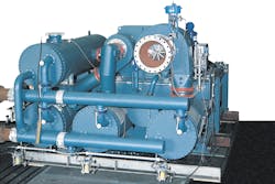
An integrally geared centrifugal compressor is a multi-shaft compressor in which each stage is a three-dimensional (3D) impeller operated at its optimum speed. This compressor type consists of a gear unit with a central bull gear and different gear pinions, which drive many impeller stages (often up to 10 3D impellers). Integrally geared compressors with high discharge pressures of up to 300 barg and capacities up to 600,000 cubic meters per hour are offered by different vendors. Machines that also combine compression stages and expansion stages are available.
Integrally geared centrifugal compressors provide many advantages such as advanced high-speed 3D impellers, relatively low costs (compared to conventional compressors) and higher efficiencies compared to other turbomachinery. They also offer near-isotherm compression with an intercooler after one or two impellers (every stage or sometimes every two stages). In other words, they currently provide the nearest possible operation to isotherm compression compared to many other compression options; therefore, they provide especially high efficiency. They are highly efficient because all stages are intercooled (isotherm compression), and the speed-increasing gear allows all stages to operate at a higher specific speed.
Another advantage of integrally geared compressors is the reduced number of stages required that still provide higher efficiency. Many modern designs allow rotor removal without disconnecting process piping. These design, operation and reliability benefits of integrally geared centrifugal compressors are discussed in this article.
Operation & design of centrifugal compressors
Older, multistage integrally geared compressors were used in plant and instrument air services and inert gas compression units, such as nitrogen or similar services, 60 to 70 years ago. These machineries gradually moved into the process side about 35 years ago. Several multistage, integrally geared compressor manufacturers have offered these units for process services (such as oil, gas, hydrocarbon, chemical and petrochemical) for approximately the last 30 years.
Compressors in process plants usually do not have spares and are considered critical equipment items. In most applications, compressor reliability is considered a high priority, and it is directly proportional to a plant’s profit. Integrally geared centrifugal compressors, particularly those that do not meet American Petroleum Institute (API) standards, usually have relatively lower reliability when compared to conventional API centrifugal compressors.
Integrally geared machines use multiple bearings, seals and gear meshes and operate at high speeds. In standard compressors, these usually cannot all be managed to achieve high reliability. Their reliability has been improved recently. Specifically, modern API integrally geared centrifugal compressors – designed and manufactured per API 617 and other applicable API standards, such as API 614 regarding lubrication oil systems – have provided increased reliability and availability over the last decade.
Some specialists suggest using integrally geared centrifugal compressors only for spared compressor applications. This might be correct for many non-API manufacturers’ standard integrally geared centrifugal compressors since they present relatively low reliability and availability making them practically unusable in critical services as unspared machineries. However, in many compression services in process applications, the compressor does not have a spare because providing two machines instead of one is not economically feasible. In other words, the cost of two integrally geared centrifugal compressors would be considerably more than one conventional API compressor.
Non-API integrally geared compressors are often maintenance intensive with relatively low reliability. In addition, because the gas is cooled after each impeller stage (or two stages), their performance characteristics and reliability depend on intercooler conditions. Many intercoolers are designed and manufactured in a compact and cost-effective manner with minimum margins to keep costs and sizes low. They may present some operational problems and performance issues.
Typically supplied with only an overall surge protection system and not individual impeller stage protection, non-API machines are prone to surging. Also intercoolers sometimes do not attain the designed heat-removal requirements. Some failures and operational issues have been recorded for these integrally geared compressors.
As very rough indications, non-API standard integrally geared compressors can offer around 93 to 95 percent availability; whereas properly designed API integrally geared compressors and API conventional (between bearings) centrifugal compressors can provide 98.5 to 99.5 percent availability. All the above-mentioned figures are estimated values, but they give an idea of what can be expected during operation.
Before an application of any integrally geared compressor including API integrally geared compressors, engineers should conduct field operating tests with a similar machine on similar gases and confirm effective operation. The reference check is an important consideration for integrally geared compressors. Requirements for gas or oil seals, varying gas composition and flow rates, and the possibility of fouling can significantly reduce the reliability of this type compressor during traditional air or inert gas applications.
Thrust loads from impellers and gears should be absorbed by individual thrust bearings on pinions or transmitted to the bull-gear thrust bearing with thrust-rider rings fixed to the pinions and bull gear. All specified operating conditions and startup conditions should be evaluated for residual thrust loads. Balance pistons are normally not used. Thrust balancing may be achieved by helix thrust force direction of the gearing and offsetting impeller aerodynamic thrust forces.
The bearing design and operation in an integrally geared compressor need great attention. Because of the very high operating speeds (in the last stages above 50,000 rpm), specially designed bearings are required, which should be tightly controlled during manufacturing, installation and operation. As a design criterion, bearing metal temperatures should not exceed 100°C at any specified operating condition. The oil inlet temperature range should be adjusted with great care. Often, the minimum oil inlet temperature could be 30°C – and sometimes 35°C. Most often, the maximum oil inlet temperature should be 50°C.
3D impellers
The geometry and design of advanced 3D impellers have significant effects on the overall performance of an integrally geared centrifugal compressor. This is because the flow development inside each 3D impeller not only determines the aerodynamic performance and efficiency of the impeller itself, but also strongly affects the performance, operation and efficiency of the downstream and upstream systems and piping – such as inlet guide vanes, diffusers (volute), integrated facilities and complex piping systems of each stage.
The flow inside each 3D impeller is highly complex and depends on the interactions between different geometrical parameters and aerodynamics factors. The flow conditions could be responsible for flow non-uniformity, a large portion of energy losses and sometimes system instability.
The flow inside an integrally geared compressor package is 3D and, therefore, complicated. It is one of the most critical aspects of these compressors’ operation. The blade angle distributions (from the inlet to outlet of each impeller) have significant influence on the impeller’s flow characteristics and overall performance and operation. Blade angle distributions can affect compressor performance, loss generation, operating range and surge/stall limits. The efficiency, operation and performance vary with the blade angle distribution.
A comparison of wall-skin friction, blade loading and hub-to-shroud loading losses should be conducted for the different operating scenarios, such as design (rated) mass flow rate and reduced (part-load) flow rates. The wall-skin friction loss usually grows as the variation of the blade angle increases because of the rise in the blade surface area.
Impeller blades, which have small variations of angle and are relatively radial, can exhibit small wall-skin friction loss because of their relatively small surface area, but they also experience high blade loading loss. Further, the flow separation near the hub at the suction side and the tip may occur. All these factors could result in relatively high energy losses and small margins to stall for these blades.
At a low flow rate (part-load operation), a flow separation region near the hub at the suction side and a vortex region near the tip might occur. The accumulation of energy loss because of unstable secondary flows is the main reason for difficulty moving through the passage with a highly adverse pressure gradient in a radial blade (relatively small variations of blade angle).
In contrast, blades that have large variations of angle, exhibit relatively large wall-skin friction and hub-to-shroud loading losses, but they experience low blade loading loss because the flow from the inlet to the outlet is usually well guided. As the flow coefficient increases, the performance of these blades (those with large variations of angle) could steeply decrease. The poor performance of blades with large variations of blade angle at high mass flow rates can be explained in terms of flow blockage at the narrow throat.
When the flow coefficients are high, blades with large blade angle variations exhibit reduced performance. At a high flow rate, an unfavorable stream line on the suction side and a low total pressure from inlet to outlet – resulting from blocked flow at the throat – have been observed in these impellers.
Gear system
The gear system is key in an integrally geared centrifugal compressor. Its complex configuration, high accuracy demand and high load operating conditions require stringent design and manufacturing criteria. The gear system is usually manufactured by a special sub-vendor (usually a well-known gear unit manufacturer) and sent to the compressor vendor for further work and completion of the compressor unit. The gear systems’ natural modes, vibration responses and generated noise levels should be properly investigated.
Two primary types of dynamic excitation in gear systems can cause excessive vibration and noise response. One is the gear meshing dynamic excitation that is an internal parametric type. This kind is unique to geared systems and arises from a combination of the periodic variation in the meshing tooth number; tooth impact forces; and transmission error because of elastic tooth deformation, gear tooth profile manufacturing error and misalignments. The frequency of this dynamic force directly relates to the tooth-to-tooth period and, therefore, shows up mainly in the mesh harmonics in the response spectrum.
The second type of dynamic excitation in gear systems is caused by an external set of dynamic shaft loads that typically occurs much lower in frequencies compared to the mesh harmonics. The sources of this dynamic excitation includes shaft rotational imbalance; shaft geometrical eccentricity; and dynamic loads from other sources such as compressor stages, driver and rotational speed, and torque fluctuations under loaded conditions.
Gear system noises and their dynamic forces are an increasingly important area for the improvement of integrally geared compressors. The noise is generated mainly at gear rotational frequency as a result of imbalance, eccentricity and swash, and tooth contact frequency (TCF) and its harmonics.
Total power loss in gear systems can be broken down into the contributions of friction between the teeth, lubrication and gear windage effects. Regarding the lubrication losses in gear systems, they are usually because of churning and jet lubrication, which could induce gas-oil trapping in inter-tooth spaces.
Power losses in high-speed gear systems come from the friction between the teeth (sliding and rolling), lubrication processes (dip or jet lubrication), pumping of a gas-lubricant mixture during the meshing, and losses associated with windage effects.
Amin Almasi is a senior rotating machinery consultant in Australia. He is a chartered professional engineer of Engineers Australia and IMechE and holds bachelor’s and master’s degrees in mechanical engineering and RPEQ. He is an active member of Engineers Australia, IMechE, ASME and SPE and has authored more than 100 papers and articles dealing with rotating equipment, condition monitoring, offshore, subsea and reliability.


