Top 5 product-specific milling technologies used in industrial applications
What do carbon black, spices, pigments, tungsten carbide and calcium carbonate have in common? Their production represents 90 percent of the size-reduction methods used to produce powder materials today: air classifying, pin, hammer, jet and ball mills.
As products and technologies become more advanced in today’s markets, the need for materials with specific properties for special applications becomes more important. With the broad range of requirements, it is not practical to think that one type of milling technology will satisfy all needs. This article provides an overview of five product-specific milling technologies used in many industrial applications today.
Many process engineers know the material characteristics they want but are unfamiliar with the specific size-reduction technology they may require. This article presents five different materials and one of the best size-reduction methods for achieving the product goal.
Determine feed material & product specifications
The most important aspect of selecting a size-reduction technology is to know some basic information about the product to be processed: feed particle size material characteristics, required particle size, and desired particle size distribution. Based on product characteristics only certain milling technologies may be suitable for a given application. Starting a project understanding these basic requirements will result in an economical and trouble-free milling system solution.
Feed particle size
Larger feed material means more residence time in the mill and larger equipment will be required for a given production capacity.
Material characteristics
It is important to know the feed material’s characteristics.
- Cohesive and sticky products may build up on mill internals and upset airflow and increase pressure drop across the mill.
- Low melt point materials are sensitive to high energy input. Heat-sensitive products may require cooling to efficiently process them.
- Hydroscopic materials absorb moisture causing buildup and plugging and may require dehumidified air for processing.
- Products containing moisture may allow for high-energy processing; the moisture in the product will absorb the heat of grinding, providing cooling in the process.
- Material hardness may lead to high component wear and increased maintenance.
- High-energy input can lead to the generation of too many fines when processing friable materials.
- Impact force tends to produce sharp angular particles.
- Compression and shear forces tend to produce more rounded particles.
- High-aspect-ratio materials are destroyed by certain size-reduction techniques.
- Hazardous, toxic or potentially explosive materials also require special system design considerations.
Size reduction techniques
The four basic techniques used in size reduction of dry powders are impact, shear, attrition and compression forces. In some cases, a combination of these may be found in a single mill type. Impact and attrition size-reduction methods include air classifying mills, pin mills, hammer mills and jet mills. Shear, impact and compression methods are used in media or ball mills.
The five types of milling technologies discussed in this article cover more than 90 percent of size-reduction applications in major chemical, food, pharmaceutical, cosmetics and mineral industries. A featured material for each is discussed to bring out the major configurations of each method.
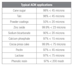
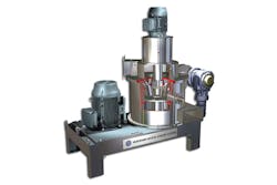
1. Air classifying mill for high-quality carbon black
For carbon black applications that require a clean, low-grit product, the air classifying mill (ACM) is the best option. The ACM has a proven track record, successfully replacing other milling technologies and achieving grit levels as low as 1 to 2 parts per million (ppm) at -325 mesh or 10 ppm at -500 mesh for many grades of carbon black. The ACM rotor is equipped with special plate hammers and a hybrid multiple deflector liner.
How the ACM works
The ACM employs two mechanical stressing mechanisms to reduce the size of the particles. The primary stress mechanism is mechanical impact caused by the direct contact of the hammers/beater blades against the fluidized powder. The secondary force is particle-to-particle attrition caused by the vortices created by the passing tip of the plate hammers close to the multiple deflector liner. The combined stressing mechanism accounts for about 80 percent impact and 20 percent attrition.
The main principle of this mill type is to use air to convey material to the mill, a rotating disc with hammers to reduce the material, air to classify the product into fine and coarse fractions, and air to convey the fines out of the mill. Coarse material is returned to the grinding chamber for further size reduction. The process is repeated on a continuous basis.
ACM configuration
ACM is a general term for many types of impact mills that also incorporate dynamic classifier technology as part of the mill design. ACMs are the most widely used milling technology in the powder-processing industry today for the general size reduction of fine chemicals and food products. The basic advantage of these mills is that they grind and classify in one step.
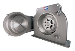
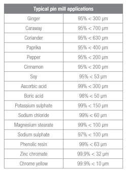
2. Pin mills for spice production
The wide chamber contra-rotating impact pin mill was originally designed for processing cocoa powder, but has since found many uses beyond that industry. Wide chamber mills perform trouble-free, ultra-fine grinding of difficult products, even in continuous operation.
Pin mills are ideally suited for size reduction of crystalline or needle-like particles and fatty or oily feed materials, which are found in both the pharmaceutical and food industries. The pin mill’s wide chamber housing prevents internal coating and blockage problems. The unit’s power requirements are lower compared to some other milling technologies, in some cases up to 50 percent lower depending on the product.
How pin mills work
The most common pin mill design is the single rotating pin disc design with stationary door disc and narrow grinding chamber. Centrifugal forces generated by the rotating disc causes the material to radially pass through a labyrinth of pins aligned in circular rows. Material is reduced in size by impact as it passes through the rows of pins. A bottom outlet is used when material is gravity discharged from the mill or a tangential outlet is used when material is air conveyed away from the mill. No screens are used in pin mills to control particle top size.
Pin mills can also be designed with counter- rotating discs, ideal for various spices with high oil or fat content; they can be processed without the need for cooling. A wide chamber design with counter rotating pins is used to process sticky materials; the wide chamber helps to eliminate any material accumulation within the mill.
Pin mill configuration
In a pin mill, the particle size is controlled by three parameters: Feed rate, rotor speed and airflow. Varying these parameters will have the following effects:
- Increasing the feed rate will result in a coarser particle size while reducing the feed rate will have the opposite effect.
- Increasing the rotor speed and impact force will generate a finer particle size while reducing the speed will have the opposite effect.
- Increasing airflow will produce a coarser product while decreased airflow will produce a finer product.
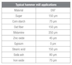
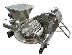
3. Hammer & screen mill for finely ground pigments
One of the best size reduction systems for fine pigment grinding is the hammer and screen mill. This pulverizer uses swing-hammers with interchangeable screens to produce a variety of products from 50 to 100 microns. The hammer and screen mill needs less air (less ancillary equipment) than the ACM and is a lower cost option for pigment processing.
How hammer mills work
Hammer mill design consists of a rotor assembly with hammers that rotate inside a cylindrical housing. The top of the housing contains a multiple deflector liner. Particles are accelerated into the liner by the impact force of the hammer. The impact breaks the particles into smaller pieces, and the liner slows its peripheral velocity and deflects them back into the hammer path for further size reduction.
The bottom portion of the housing contains a screen. The screen is used to control the size of the particles exiting the mill. Various screen types and hole sizes are used to change the final product particle size.
Hammer mill configuration
The three basic types of hammer designs are: The stirrup or LFS hammer, the swing bar hammer and the rigid bar hammer. The stirrup hammer has the most surface area and is used at high speeds to produce the finest particle sizes. The swing bar hammer is used on materials that do not respond well to impact. Fibrous materials that need to be cut or shredded work well with this type hammer. The rigid bar hammer is used for granular and coarser size reduction applications and for producing narrower particle size distributions when a minimal amount of fines generation is desired. Each of these hammer types has wear-protected tipping added to prolong wear life.
Controlling particle size and particle size distribution can be accomplished by employing a variety of different screen types and hammer designs. The sizes of the screen perforations and slots come in many dimensions. Round-hole screens produce the finest grinds, but herringbone and cross-slot screens are employed to process sticky or fibrous materials.
4. Jet milling for tungsten carbide
Because of its operating principle, the jet mill can handle extremely abrasive materials as particles are impacted against each other and not against the internal components of the mill. It is suitable for ultra-fine size reduction of extremely hard materials such as tungsten carbide with a Mohs Hardness of 9.5.
For the processing of extremely abrasive materials, these mills can be lined with ceramics or polyurethane. New technology allows for the high wear components, particularly the classifier, to be made in silicon carbide or a completely cast aluminum oxide wheel, providing thousands of hours of service life when processing abrasive materials.
How jet mills work
The jet mill design incorporates a grinding zone at the bottom of the mill. The classification zone is located in the top section of the mill. Feed material is introduced to the mill through a top gravity feed inlet.
These mills work by accelerating gas through a nozzle directed to a central focal point. Multiple nozzles are used to generate a grinding zone at the center of the mill. The material bed height in these mills will completely cover the nozzles during operation. Only gas and not product passes through the nozzles. The high-velocity gas entrains the material in the bed and the combined gas/material mixture is directed to the central grinding zone. Particle-on-particle collision is responsible for size reduction. Fine material is carried by the upward flow of air to the classifier wheel where material ground fine enough exits the mill and oversize material returns by gravity to the bed.
Jet mill configuration
All jet mill designs incorporate a radial nozzle arrangement with the number of nozzles used varying with mill size. In general, the larger the mill, the higher the quantity of nozzles utilized to introduce the correct volume of air required for grinding. Different types of nozzles are also available depending upon the requirement of the application.
The classifier in the jet mill is used to change particle size. However, there are other options to achieve the desired particle size when more than classifier speed is required. For example, while maintaining grind air pressure and classifier speed, the use of smaller diameter grinding nozzles will produce a finer product.
Ball mills for super-fine calcium carbonate
Ball mill classifier systems have been improved over time and are now capable of achieving much finer products. In the past, a particle size with a D97 of 10 microns was only possible. Now particle sizes down to a D97 of less than 3.5 microns can be achieved, with a D50 in the range of 1.5 microns.
This improved performance is made possible by the optimization of all ball mill system’s parameters, including the incorporation of a high-performance classifier, improved control systems and grinding aids.
A closed-loop ball mill/classifier circuit can be positioned on load cells for weighing the total mill content of media and material. Incorporation of load cells represents the latest technology for controlling the feed rate to the ball mill. By controlling the mill weight, the optimal amount of material is always in the mill bed and the milling efficiency is optimized by never under- or over-filling the mill. The classifying air volume is measured and kept constant by the use of a thermal mass flowmeter and control device, to assure a consistent product quality.
How ball mills work
A ball mill grinds material by rotating a cylinder filled with media (typically metallic or ceramic balls) mixed with a continuous flow of feed and recycled material. At slower rotational speeds, the grinding media creates a cascade motion where the media is mainly rolling and shear forces for grinding are generated. When the speed of the mill is increased, a cataract motion (cascading or breaking wave action) is generated where impact forces develop as the media is lifted and falls back onto the media/product bed.
The ideal condition is to operate at the transition point between these two flow patterns in the mill to utilize both effects. This condition is reached at about 60 to 80 percent of the critical speed of the mill where the centrifugal force is high enough to prevent the media from completely falling back down on the material bed.
Ball mill configuration
Ball mills use shear and impact milling techniques. Ball milling uses shear forces when particles are stressed between two surfaces that are moving in opposing directions. Particles experience impact forces as they fall against the media. A number of processing parameters influence the performance and efficiency of a ball mill classifying system including:
- Speed can be varied by use of frequency converters to optimize performance.
- A longer drum will lead to a product with higher fines content.
- Selection of grinding media including cylpebs or ball media in steel or ceramic.
- Sizing of cylpebs or ball media depends on the end product fineness and also the feed size.
- Selection of the mill lining; for soft minerals usually steel linings are used, sometimes with a high chromium content option, which reduces material discoloration. In some cases, a ceramic lining is used if the highest whiteness or brightness is needed or to eliminate iron contamination.
Conclusion
Many size-reduction technologies are available from many suppliers around the world. Some are multifunctional and can process a wide range of materials. With all these options, it is helpful to learn a little about some of the milling systems that address the widest range of materials and the widest range of particle size and capacity.
Rob Voorhees is president of Hosokawa Micron International Inc. Voorhees started his career with MikroPul Corporation, an air pollution control and environmental company that was acquired by Hosokawa in 1985. He later worked as regional sales manager for Research-Cottrell Corp. In 1994, he rejoined the Hosokawa Micron Group. Voorhees held various sales and management positions until becoming general manager in 1998. He received a bachelor’s of science in Industrial Technology from Montclair State University and has participated in an Executive Management program at Dartmouth University. He may be reached at [email protected] or 908-273-6360.