Automating valves for system integration
Automated valves have become a bigger part of today’s process control systems as users develop processes that reduce manual valve operation. With the extensive range of control devices, protocols and process area standards and restrictions, it is helpful to have a comprehensive guide to discuss options available for virtually any quarter-turn valves.
As more valve manufacturers are producing their designs to accommodate valve automation, there are many more methods and options for precise control of both on/off and modulating control valves.
How to select automation accessories for valves
Today's process controls range from complete computer systems to the staff-monitored electromechanical type (push buttons, heavy-duty relays, etc.). In the process area, there may also be pressure switches temperature controllers or other process-monitoring devices that must tie into the control valve and therefore the actuator.
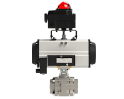
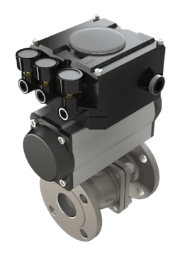
The pneumatic actuator is the workhorse for the automation of quarter-turn valves. When selecting a pneumatic rotary actuator for valve control in process applications, it is important that it be compatible with other components of the control system (power medium, control signals, etc.), the environment (corrosion, temperature), the system (speed, cycle frequency, fail mode) and, of course, the valve.
To work well with an existing control network, the pneumatic actuator must be available with a few basic control accessories.
- Solenoid valve: As a pilot device, available in various voltages and construction for the area classification.
- Limit switches: For indicating valve position, sequence cycling, alarms, etc.
- Positioner: To throttle the valve in response to a varying control signal.
For environmental compatibility, the actuator should be available with corrosion-resistant (anodized, stainless-steel) trim, various coatings (polyurethane, epoxy, etc.) and weatherproof, hazardous-area or intrinsically safe control accessories.
Pilot valve
A pilot valve for a pneumatic actuator is a control device that receives a manual or power signal and then directs air pressure to the air inlet ports of the actuator to drive it to the desired position. The most common type of pilot device is the solenoid-operated valve. As an electric device, it readily interfaces with widely used control systems and may also be supplied with low-wattage coils for compatibility with computer control signals.
Pilot valves for pneumatic actuators are categorized by the number of port openings or ways air may flow through them.
For instance, a three-port (three-way) valve has a pressure port, output port and exhaust port. The three-way valve is a logical choice for spring-return pneumatic actuators because only one air chamber is alternately pressurized or exhausted in normal operation.
A four-way valve has a pressure port, two output ports and an exhaust function. The two output ports will pressurize one or the other chambers of a double-acting cylinder, so it is used with these types of pneumatic actuators.
Limit switches
For a pneumatic actuator, the term limit switch may be a misnomer. The term more properly applies to electric rotary actuators that are fitted with limit switches to interrupt the power to the motor when the actuator has reached its desired limit of rotation. As a functional term, “position-indicating switch” (or feedback switch) is more properly applied to limit switches when they are used with pneumatic actuators.
Indeed, a switch fitted to a pneumatic actuator does not limit its travel but instead indicates (through switches) when the actuator has reached, or has not reached, a specified point of rotation.
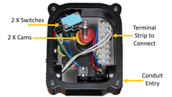
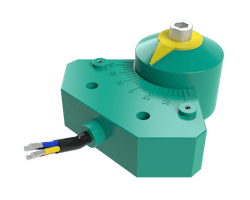
Also referred to as a switch box, the position-indicating switch box encloses the switch elements, cams and terminal strip, and it has a rotating input shaft that is fitted to the auxiliary shaft of the actuator to pick up rotary motion. The switch housing is composed of an input shaft that externally couples to the actuator's auxiliary drive shaft and is fitted internally with adjustable cams, snap-acting switches that are mounted to align with the cams, and a terminal strip for incoming wiring. As the actuator cycles, the input shaft of the switch box rotates, and the cams actuate the switches. When the switches are used to indicate the limits of the cycle, the cams are adjusted to operate the switch when the desired position is reached.
Position-indicating switches are used for a variety of applications: light indication (powering indicator lamps on a control panel), system sequence cycling, alarms, electrical interlocking, etc. Some switch enclosures may be fitted with other devices, such as a potentiometer or position transmitter for continuous feedback of the valve's position.
When the switches are connected to signal lights, they should be arranged so that both lights are on in mid-travel, with one or the other being extinguished at the ends of travel. This helps the operator avoid being misled by a burned-out lamp.
Switch boxes for pneumatic actuators are often specified by the type and quantity of switches required. Examples of the types of switches available are mechanical (snap acting) and proximity.
Mechanical switches
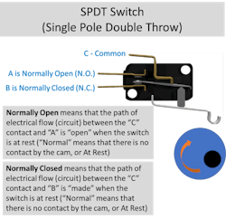
These switches are also called “snap acting” switches as there is a distinct sound (snap) as the contacts shift within the switch.
Mechanical switches are usually expressed in terms of the number of poles and throws they contain. A pole is a component of the switch that is moved by the switch action to make or break electric contact. The possible electric connections that can be made by a given pole are called throws.
There are four configurations of electric limit switches: single-pole-single-throw; single-pole-double-throw; double-pole-single-throw; and double-pole-double-throw.
Proximity switches
These switches/sensors operate when a metallic or magnetic object is brought into proximity with the switch sensing area. These switches are inherently protected against dust and moisture and some require a power circuit. Two types of proximity switches are the proximity sensor and reed switch.
Inductive sensors
Inductive sensors are switches that operate when a metallic object is brought into proximity with the sensing face. Most inductive sensors comply with several NEMA ratings. The sensors are protected against dust, moisture and oil. Internal solid-state circuitry prevents shock and vibration from affecting sensor operation. They require power to operate as the sensing area is a field of electro-magnetism.
Reed switches
Another low-current proximity switch (250 to 500 mA) is the reed switch. Action is initiated when a magnet is placed in the proximity of the sensing area. Reed switches do not require a power supply.
Major advantages of reed switches:
- Fully hermetically sealed metal contact.
- Reed switches can operate in moist and dust ambient conditions.
- Temperature variation from -60°C to +155°C (-76°F to 311°F).
- Zero power to operate.
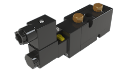
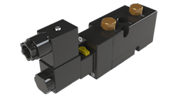
A fully integrated solution
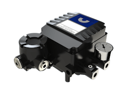
Because it is common that both a feedback limit switch and a pilot valve are part of a typical automated valve package, there are fully integrated devices that incorporate both of these elements into one enclosure. A good example is the Nexus-LP from SVF Flow Controls.
At least one advantage of this product is that the field wiring connects through a single conduit entry, tying both the pilot valve power wiring and the feedback terminals of the limit switches.
Other methods of position indication
If continuous monitoring of an actuator's position is required, as in modulating or "jogging" applications, a switch box may be fitted with a potentiometer. As the shaft of the switch box rotates, it likewise rotates the input shaft of the potentiometer. The continuously decreasing or increasing resistive signal may then be converted into a valve position at the control panel. When the actuator is located far from the control system, the result may be an unreliable resistive signal due to the inherent resistance of the long wire. In this case, a resistance-to-current transducer circuit may be preferred. The circuit board is usually installed in the switch box with the potentiometer and provides a 4-to-20 mA signal to continuously indicate valve position.
Electrical enclosures
Switch boxes designed for use in explosive environments (hazardous areas) must be able to withstand an internal explosion without igniting the explosive mixture surrounding the switch enclosure. The enclosure is thus designed to withstand the maximum expected internal explosion pressure without damage or excessive distortion and to provide venting for the pressure through channels of such dimensions that gases will be cooled below the ignition temperature before reaching the surrounding atmosphere. Thus, the design of a hazardous area switch enclosure involves careful consideration of housing thickness, cover fit and tolerances.
Many switch enclosures incorporate multiple construction standards that are listed by the National Electrical Manufacturers Association (NEMA IV, VII, IX, etc.) to satisfy a wide range of applications. Hazardous area device selection and area definitions are also covered by ATEX.
Selecting controls for modulating valve applications
Pneumatic positioners
When a valve is used for modulating/throttling rather than simple on-off service, it may be considered a rotary control valve. A control valve is a process control element that varies the flow of fluid as required by a process in response to a system control signal. To provide fast, sensitive and accurate positioning in response to a control signal, an actuator must be fitted with a pneumatic positioner. A pneumatic positioner is basically a relay that senses and compares an instrument signal and the valve stem position. Because it is usually mounted to the top of a rotary actuator, it senses valve position through the actuator shaft.
Most basic positioners have linear characterization. This means that the input signal to output rotation is directly proportional, which enables the process engineer to select a valve that will provide system characteristics. Standard ball valves, for example, provide equal percentage flow like many other quarter-turn valves do.
Terms associated with positioners
- Direct acting — Increasing input signal opens the valve (increases flow).
- Reverse acting — Increasing input signal closes the valve (decreases flow).
- Resolution — The smallest possible change in valve position.
- Deadband — The maximum range through which the input signal can be varied without initiating change in valve position.
- Hysteresis — The maximum difference in valve position for a given input signal during a full range traverse in each direction.
Transducers
A transducer is a device that converts one signal type to another. In the case of control instrumentation, a current-to-pneumatic transducer accepts an analog milliamp control signal from a field instrument and converts it to a proportional pneumatic signal for the positioner. The most common conversions used with control valves are for systems being controlled and monitored with electronic instrumentation but with pneumatically actuated control valves. The use of a transducer is the most practical method for interfacing the two types of equipment. As an electromechanical device, a transducer must be carefully selected for environmental compatibility, hazardous areas, sensitivity, vibrations, etc.
One drawback of transducers is that it is sometimes difficult to locate them near the positioner, which may then require long runs of wire or pneumatic tubing. To satisfy this, some manufacturers have integrated the transducer into the positioner. These hybrids are known as electro-pneumatic positioners.
Standard instrument signals
Instrument signals are used to interface between various elements in the control process. Information may be transmitted from a sensor to a controller, or a controller to an actuator, etc. Standard instrument signals allow a wide variety of products made by different manufacturers to work together. Common standard instrument signal ranges are shown below.
The high end of a standard instrument signal range is usually five times the value of the low end. For instance, 20 mA is 5 × 4 mA, 15 psi is 5 × 3 psi, etc. The low end usually does not have a value of zero. This provides a positive method of determining the difference between a device that is indicating the low end of a range and a device that is not functioning. This is known as live zero.
The main exceptions to these conventions are resistance-type inputs, which usually have a low end of zero and various values of high ends.
Split ranges are usually fractions of standard instrument signals. For example, 3 to 15 psi is often split into 3 to 9 psi and 9 to 15 psi, each of which is half of the standard range. Split ranging is a process by which the input signal range [3 to 15 psi (0.2 to 1 bar)] is used to pilot two control valves. In practice, the first control valve cycles through its full stroke in the range 3 to 9 psi (0.2 to 0.6 bar), and the second valve strokes through the 9 to 15 psi (0.6 to 1 bar) range.
In pneumatic devices, pressure [psi (bar)] is the usual variable for instrument signals. In electric devices, the variable may be current (mA), DC voltage (VDC) or resistance [ohms (O)]. Table 1 gives instrument signal ranges for pneumatic and electric devices.

Uses of a pneumatic positioner
The following are some uses of a pneumatic positioner.
- Temperature control
- Level control
- Split ranging
- Loops with slow response
- Reverse action relative to actuator
Note: Split ranging is a process by which the input signal range [3 to 15 psi (0.2 to 1 bar)] is used to pilot two control valves. In practice, the first control valve cycles through its full stroke in the range 3 to 9 psi (0.2 to 0.6 bar), and the second valve strokes through the 9 to 15 psi (0.6 to 1 bar) range.
Positioners are available in a variety of materials of construction, accessories, characterized cams, position transmitters and integral transducers.
Manual override devices for pneumatic valve actuators
In this era of automation, it is possible to have more control over a process system than ever before. In fact, when the decision is made to automate a valve for a specific function or functions in a system, one important reason is to have even more complete control over the process by providing feedback, sequencing and rapid response and by eliminating human error.
Interfacing an automated valve with a control system may require that an actuator be equipped with a solenoid-actuated pilot valve, positioner, limit switches, a mechanical position indicator, transducer and so many other control accessories that if there is a loss of power to the actuator, or if the actuator fails to operate for any reason, it may be rendered inoperable and therefore useless, becoming a potential hazard or causing an unnecessary shutdown of the production process. In effect, control of the valve and possibly the entire process may be lost.
The simplest and most reliable method for guaranteeing the continued operability of an automated valve in the event of a system failure is to use a manual override device. As more quarter-turn valves are being incorporated into expanded process control systems, there is an increased concern over the ability to operate these traditionally manual valves in the event of actuator or power failure. This concern has been recognized and addressed by actuator manufacturers. There are currently a number of manual override provisions available for pneumatic quarter-turn actuators.
Wrench override
A wrench override is simply a handle with an engagement provision that fits to the auxiliary drive shaft of the actuator. Upon failure, the wrench may be applied to the flats of the shaft to manually override the actuator. This method should be used only with double-acting actuators as it is difficult to override and hold spring-return actuators in position. Torque should be limited to about 1500 lbf-in (170 Nm).
The wrench is usually attached to the actuator or mounting bracket with a cable or chain to prevent loss. It may also be available with a locking provision to hold smaller spring-return actuators in position until the problem is resolved. A wrench override should never be permanently attached to the drive shaft of the actuator because, when it operates automatically, it may cause injury to personnel working near the equipment.
Disengageable gear manual override
The disengageable gear override is a modular component that fits between the valve and the actuator and offers simple and reliable manual positioning. The self-locking worm gear design provides for safe and easy operation and positive manual positioning even with spring-return actuators. Rotating the clutch lever, located at the base of the handwheel, 180 degrees immediately engages the worm gear with the output drive sleeve to permit operation. Manual override modules may be adapted in the field to existing control valves with a slight modification to the actuator.
Manual overrides have proven to be an accessory requiring greater consideration in many applications. Modular construction, immediate operation and adaptability to standard actuators are important to consider.
Two-wire control (As-I)
An increasingly common technique for controlling and communicating with automated valves in process areas is two-wire control.

Based on various bus protocols (DeviceNet, As-I, etc.), there are a variety of systems that cover simple on/off valve control to full system integration, diagnostics and control. The choice becomes a plant/platform-wide decision.
AS-Interface (Actuator Sensor Interface, AS-I) is designed for connecting simple field I/O devices (such as actuators and valve position sensors) in discrete process applications using a single 2-conductor cable.
AS-Interface is an “open” technology supported by a multitude of automation equipment vendors. It is a networking alternative to the hard wiring of field devices, and it can be used as a partner network for higher level fieldbus networks such as Profibus, DeviceNet, Interbus and Industrial Ethernet. It offers a low-cost remote I/O solution.
Applications: Systems that utilize eight or more valve actuators can benefit from bus technology. Typically, these systems have automated valves controlled by a programmable logic controller (PLC).
AS-Interface versus conventional system
AS-Interface is a versatile, low-cost alternative to traditional hard-wired I/O. It can replace traditional point-to-point wiring with a better, more flexible solution that is easier to install, operate and maintain, as well as easier to re-configure.
Conventional system
Typical batching valve wiring networks attach each of the inputs and outputs (I/O) to a central location resulting in multiple wire runs for each field device. Large expenditures are needed for cabling conduit, installation and I/O points. Space for I/O racks and cabling must be accommodated in order to attach only a few field devices.
AS-Interface network
A simple gateway interfaces the network into the field communication bus. Data and power are transferred over the two-wire network to each of the AS-Interface compatible field devices.
Each valve communication module contains an AS-Interface ASIC and other electronics to gather open or closed position status and power solenoid or other ancillary devices on or off. Other AS-Interface modules are available to gather inputs and switch power outputs.
AS-Interface features:
- Ideally suited for on/off batch process valves and other discrete applications.
- 62 field devices per network master.
- Simple electronics for economical and robust performance.
- Transfer medium is unshielded two-wire cable for both data and power supply.
- Signal transmission has high tolerance to EMI.
- Easy to install, providing the greatest cost savings with the least complexity.
- Free choice of network topology allows optimized wiring network.
- Variety of gateways available to seamlessly tie into high level bus networks.
Conclusion
A process control scheme will likely be developed for very specific outputs, rates and materials. It may also need to address pressure and temperature conditions and hazardous area locations. With the many options, classifications and control solutions available today, it is always a good idea to work with a highly experienced automation supplier.
Wayne Ulanski is the president of SVF Flow Controls and the author of the technical book, Valve and Actuator Technology (McGraw-Hill). He has been an influential member of the valve and actuator community for many years. SVF Flow Controls is the engineered flow control division of Matco-Norca LLC.
SVF Flow Control
About the Author
Wayne Ulanski
president of SVF Flow Controls
Wayne Ulanski is the president of SVF Flow Controls and the author of the technical book, Valve and Actuator Technology (McGraw-Hill). He has been an influential member of the valve and actuator community for many years. SVF Flow Controls is the engineered flow control division of Matco-Norca LLC.