When an upstream process operates at a higher pressure than the processes, flows and equipment downstream from it, there is risk of over-pressurization, resulting in a rupture or explosion. Historically, refineries and chemical processing plants have relied on relief valves to exhaust gas into the air when pressures got too high. However, environmental regulations limiting emissions make this impractical. Exhausting pressurized gas to air also raises safety concerns.
Another option is to beef up downstream equipment to withstand higher pressures than processes require, but that drives up costs and may not even be feasible within the design footprint.
The current state-of-the-art solution is a high integrity pressure protection system (HIPPS). A HIPPS is a functional — not passive — safety system. This means it operates to achieve a safe state. A HIPPS includes sensors, a logic solver and final elements — solenoid, actuator and process control valve — to shut off the source of over-pressure. A HIPPS is designed to act as quickly and reliably as a relief valve without the environmental and safety issues.
Safety Integrity Levels
The industry standards for HIPPS are IEC 61508 pertaining to "functional safety" and IEC 61511 pertaining to "safety instrumented systems for the process industry sector." These standards define different levels of functional safety requirements based on the likelihood that a system will fail when it is needed — "probability of failure on demand (PFD)." Risk is defined as PFD multiplied by the cost of the consequence of failure. In other words, if the consequence of a failure is very costly (for example, injury or even death) the probability of it happening must be reduced to achieve an acceptable level of risk. The IEC standards define levels of risk reduction, identified as Safety Integrity Levels (SIL). SIL 1 denotes risk reduction by a factor of 10. HIPPS are typically rated SIL 3, requiring risk reduction by a factor of at least 1,000.
When a sensor detects possible over-pressurization, it sends a signal to the logic solver, which activates the solenoid. The solenoid controls the flow of compressed air or gas to the actuator, which in turn moves the process control valve to the safe position, shutting down the process.
This whole system must be rated SIL 3 by an independent testing organization such as TÜV. For a HIPPS to be certified SIL 3, the PFD of all the components working together must conform to SIL 3. Note that some systems may be referred to as SIL 3-capable because they include components suitable for SIL 3 environments, but to be certified SIL 3, the system as a whole must meet the standards.
Redundant solenoid valves
Clearly, if a process were controlled by a single solenoid valve and that valve failed to function, the result would be catastrophic. Besides using a solenoid valve with a PFD suitable for SIL 3, risk must be further reduced by using multiple valves backing up each other in a redundant system.
There are various levels of redundancy and each has implications for process industries. In the case of one out of two (1oo2) redundancy, there are two normally closed valves installed to control the process valve. While they are energized they remain open to keep the process flowing. In an emergency, they de-energize and default to closed. If one fails to close during an emergency (a "dangerous" failure), the other will close and shut off the flow of volatile media.
However, if a valve fails and shuts down the process even though there is not an emergency (a "safe" failure) it can cost millions of dollars a day and cause significant business and operational disruption. A two out of two (2oo2) redundant system will reduce the risk of these spurious trips by ensuring that one valve remains open even if one valve fails and closes without cause. However, once this
happens, the system is no longer redundant to protect against a dangerous failure.
For both safety and process availability, a two out of three (2oo3) triple-channel redundant system offers the best balance. If one valve fails and de-energizes, defaulting to the closed position, the two remaining valves function as a 2oo2 system, ensuring process availability. If one valve fails and sticks open, the remaining two valves function as a 1oo2 system, ensuring that the process can be shut down in an emergency, thus protecting safety. A four-channel valve system increases the probability that 2oo3 redundancy will continue in place.
To achieve SIL 3, redundancy to prevent dangerous failure is required. This means only 1oo2 or 2oo3 redundant valve systems qualify, not 2oo2.
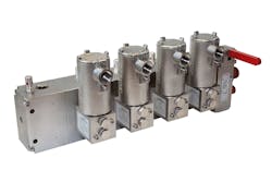
A four-channel redundant valve manifold integrates valves with all necessary piping, reducing size, complexity and potential leak points to maintain 2oo3 redundancy.
Why a manifold?
Complexity is one of the challenges facing designers who want a redundant valve HIPPS. The more solenoid valves there are, the more piping and fittings are needed. The typical system has each solenoid mounted individually, with piping and connections bolted together on a back plate or tie-rodded together. Not only does this result in a large assembly footprint, but it also creates multiple sites for potential leaks or other faults, making it difficult for the whole system to be certified SIL 3. The complexity of this design also makes installation more challenging and multiplies maintenance requirements.
A new solution gaining popularity is to integrate the valves and piping into a single manifold unit. Stainless steel valves are mounted on a stainless-steel manifold that incorporates all necessary piping. Redundant valve manifolds for each critical process are mounted in a cabinet for a SIL 3-certified HIPPS.
The manifold solution offers an additional way to reduce risk; using solenoid valves of different designs. This valve diversity means that should one type of valve be vulnerable to an unanticipated systematic problem in a design, the other valve will not be because of its different design.
Manifolds also allow designers to work with the supplier to customize features. For example, the manifold can be designed with a bypass function so valves can be tested or serviced without shutting down the process. Mounting connections, valve types and manifold shape and material can all be customized to meet an end user’s specific requirements.
Using redundant valve manifolds in HIPPS helps oil and gas producers meet IEC standards and keep their plants, employees and communities safe.
Abby Sanchez is global key account manager – Energy Sector for IMI Norgren, an IMI Precision Engineering branded company. With degrees in engineering and business, she offers cross-functional expertise in application engineering, new business development and customer relationship management to the oil, gas and petrochemical industries.

