How digital valve positioners can simplify safety life cycle phases

Safety systems with emergency shutdown, venting, isolation and other types of safety valves (see Figure 1) require each valve to close or open immediately when a process upset or emergency occurs. If this doesn’t happen, the result could be a dangerous condition leading to an explosion, fire and/or a leak of lethal chemicals and gases. For example, a safety shutdown valve, in a specific refinery application requiring process safety time of less than 2 seconds, must close in 2 seconds to stop fuel flow. If it doesn’t, a catastrophic failure could occur, leading to unknown damages.
Emergency valves are not continually opening, closing or throttling like a typical control valve — but instead normally remain in one static position for long periods of time, and are expected to operate reliably when an emergency occurs. Valves that remain in one position for long periods are subject to becoming stuck and may not operate when needed. To ensure their required reliability and availability in safety systems, they need to be tested frequently.
Unfortunately, the traditional method of testing the final element of a safety system requires a shutdown, and/or for the safety system to be rendered inoperable during the time the valves are being tested — both undesirable and expensive options.
This article discusses safety life cycle (SLC) as described in the International Electrotechnical Commission (IEC) standards IEC61508 and IEC61511 and various phases including longest operation and maintenance phase. To meet validation and verification stage of SLC, it will demonstrate how modern digital techniques are becoming a remedy to simplify testing.
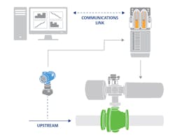
Figure 2. Partial-proof testing can be accomplished on line with a digital valve controller. A logic system (top left) or asset management system (AMS) commands the digital positioner (bottom right) to execute the test, and logs all the test data obtained by the positioner.
The 20:20:20 rule
The 20:20:20 rule applies to the entire SLC of a safety instrumented system (SIS): the Analysis Phase typically takes 20 weeks, the Design Phase takes 20 months and the Operation Phase takes 20 years.
In the Analysis Phase, the valve designer first performs a SIS risk-tolerance analysis to determine what level of safety is needed and what hazards can be expected. IEC and the International Society of Automation (ISA) standards specify precise levels of safety that must be obtained, and further demand that plants furnish quantifiable proof of compliance. These standards use safety integrity levels (SILs) to quantify safety performance targets for safety instrumented systems. SILs define the level of risk in a process from SIL1 to SIL3.
In the Design Phase, the valve designer must specify a Final Element (valve) that will provide the required SIL suitability.
In the Operation Phase, the valve is continuously proof-tested to ensure proper operation.
The Operation Phase spans the longest time of the SLC in which all safety instrumented functions (SIFs) must remain in operation to maintain the desired SILs.
Avoiding a shutdown
Typically, a SIS consists of a logic solver, sensor and final element — in this case, the final element is a valve. Unlike the logic system and sensor, which can be tested continuously on line, proof testing the final element requires movement. The only sure way to proof test a valve completely is with an in-line test that strokes the valve from 0 to 100 percent (full open/full close). Unfortunately, stroking a shutdown valve completely often requires a total shutdown of the process, causing a significant loss in production. Operations managers usually wait to test the valves until a scheduled plant shutdown.
In the past, plant turnarounds were scheduled every two to three years. However, with increased system reliability and more inclusive predictive maintenance programs, turnarounds at many plants are now being scheduled to occur every five to six years. This means safety valves are tested less frequently, which may prevent them from meeting the target SIL.
In an attempt to extend plant turnarounds, many valve companies have devised methods for testing SIS valves on line so they do not have to shut down the process.

Figure 3. For safety reasons, an operator must start the partial-proof test, either locally or remotely.
On-line proof testing
Two methods are available for testing valves on line without shutting down the process. The first involves installing a bypass valve around the safety valve. This allows steam, gas or liquid to flow around the safety valve while technicians exercise it to ensure proper operation.
Although bypassing the safety valve during testing is done to improve the probability of failure on demand (PFD), not all parts of this testing approach contribute to this goal because the time the system remains in bypass must be considered in the PFD calculation. For long bypass periods or frequent testing, the negative impact on PFD can be significant.
A better solution for on-line testing is partial-proof testing by digital device. Safety engineers recognize the most likely failure mode of a discrete shutoff valve is remaining stuck in its normal standby position. Testing for this type of failure requires stroking the valve only a small amount to verify it is not stuck. This partial-stroke technique can detect a large percentage of potential valve failures. Furthermore, performing this type of test on line without shutting down the process can improve the PFD without a loss of production.
So-called "smart" positioners (see Figure 2) have become popular in recent years to perform these types of tests, and to provide other benefits. These are microprocessor-based, digital valve controllers that operate the valve, and use the HART communications protocol to give easy access to information critical to process operation.
In addition to this, the digital valve controller receives feedback about valve travel position, along with existing supply and actuator pneumatic pressures. This allows it to diagnose not only itself, but also the valve and actuator to which it is mounted.
Typically, the partial-stroke test moves the valve 10 percent from its original position, but it can be up to 30 percent if allowed by plant safety guidelines and the particular requirements of the process. Even though partial-stroke testing does not eliminate the need for full-stroke testing — which is required to check valve seating, etc. — it reduces the required full-stroke testing frequency to the point where it can most likely be tested during the next plant turnaround, even if it is five to seven years away.
Because the digital valve controller communicates via the HART protocol, the partial-stroke test can be initiated from a HART handheld communicator, from a personal computer running the positioner companion software, from a panel-mounted pushbutton hardwired to the positioner terminals or from any automation system supporting the HART protocol. Since the testing sequence is completely automatic, it eliminates errors and possible nuisance trips. For safety reasons, an operator is required to initiate the test sequence (see Figure 3).
The partial-stroke technique, along with the automated routine provided by the smart positioner, allows testing to be done more frequently.
The digital valve controller provides diagnostic as well as positioning information, allowing the valve status and response time to be monitored during the test. Valve performance trends can be monitored and analyzed after each partial-stroke test.
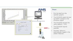
Figure 4. Emerson’s Fisher ValveLink software runs the test, diagnoses the results and produces a report. This graphic shows the sequence of events in a partial-proof test of a rotary 90-degree valve fitted with a Fisher DVC6200 digital controller.
Valve diagnostics during testing
Most major valve manufacturers offer supporting software for partial-proof testing. Software available today can run the test (see Figure 4), diagnose the results and produce a report.
When the operator commands a partial-proof test, the software’s spurious trip protection pressure limit function checks the output pressure threshold, and will abort the partial-stroke test if it is exceeded. This prevents the actuator from completely exhausting pressure and potentially causing a spurious trip in a sticking-valve scenario.
If the pressure is within limits, the software then sends a command to the valve to open or close 10 percent, records the pertinent data and returns the valve to its normal standby position. And, because the digital positioner is equipped with position and pressure sensors, it can also measure valve stiction, pneumatic pressure required to move the valve, the speed at which the valve moves, air leaks and many other parameters.
Valve diagnostic tests enable condition and performance monitoring of the entire valve assembly — not just the digital valve controller. Diagnostic data is gathered automatically to be used for troubleshooting. Examples of identifiable issues are:
- Valve stuck
- Solenoid stuck
- Low air supply or pressure droop
- Dirty air supply
- External air leak (actuator diaphragm or tubing)
- Piston actuator O‐ring failure
- Excessive valve assembly friction
- Low valve assembly friction
- Broken actuator spring
- Broken valve/actuator shaft
- Corroded bearing
- Permanent set of spring
- Linkage breakaway friction
- Slow air exhaust
- Air exhaust path blocked
- Spring-return actuator dented not allowing
valve travel - Increased valve breakaway friction
- Actuator stem/shaft bent
- Increased friction of closure element in seal
A detailed description of the identified issue as well as suggestions for recommended actions are provided.
A time and date stamp on all tests and reports aids compliance with regulatory requirements.
Benefits
While the smart positioner provides performance and safety benefits through automated, on-line partial-stroke testing, many additional benefits can be realized. These include eliminating expensive pneumatic test panels, reducing manpower requirements, lowering base equipment cost and shortening testing time. In addition, remote testing results in fewer maintenance trips to the field, as well as the establishment of an automated test routine.
Digital valve controllers improve predictive maintenance by providing a valve degradation analysis, particularly important for critical valves in safety-related systems. Improving predictive maintenance can reduce the amount of scheduled maintenance by allowing valve assemblies to only be serviced when required, instead of on a time-based schedule. Unscheduled maintenance can also be reduced because many failures can be predicted well in advance.
A smart positioner provides a time and date stamp on all tests and reports, which is very important for complying with the requirements of statutory authorities. It also provides the capability to compare and interpret diagnostic data.
Considering all benefits, the use of smart positioners in an SIS is a sensible and economical pathway to enhanced SIS reliability.

Riyaz Ali is senior director of the Instruments Business Unit at Emerson Automation Solutions, Houston, Texas. He holds a Bachelor of Engineering in Chemical Engineering with special work on digital valve controllers for process industries. Ali has been in the process control instrumentation field more than 40 years and holds various U.S. patents related to the use of digital valve controllers for process industries. With Emerson since 1993, he implements microprocessor-based technology for field devices in process control and safety applications.