Using software to pull the plug on pneumatic conveying system issues
Specialized software is an important part of every bulk materials handling (BMH) engineer’s toolkit. It is essential when working on designing transfer points with discrete element modeling, designing BMH equipment, troubleshooting pneumatic conveyors and numerous other applications. Every good engineer has a bunch of in-house spreadsheets for specialized calculations, right?
Pneumatic conveying system software is an engineering accelerator and dashboard that shows how a system should behave under a set of assumptions and conditions. The software makes it easier and faster to “see things” that would otherwise require a great deal of manual calculation. However, a thorough understanding of the software and its limitations are required to ensure accurate results.
A recent study involving a pneumatic conveyor (designed by a third party) is a good case in point. The conveyor was handling small polymer pellets in a 700-foot-long pipeline, but the line was plugging at approximately two-thirds of the way along the conveying pipe. There were no unusual bends, pipe diameter changes or other issues that would cause the material to plug. The material was dry, and the equipment supplier had chosen the permeable dense phase mode to convey the pellets at a low velocity. This mode was selected to prevent degradation of the polymer pellets, which could occur at higher speed when the particles rub against the pipe’s inside wall or impact its elbows.
The three main modes for conveying permeable material are dilute mode, mixed mode and permeable dense phase mode. In dilute mode, the material-to-air ratio is very low, and air velocity is well above the material’s saltation velocity, which keeps the particles in suspension throughout the entire cross-section of the conveying pipe.
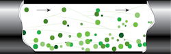
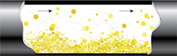

Mixed mode takes place at lower air velocities than dilute mode, below and above the material’s saltation velocity. Most particles are sliding at the bottom of the pipe in an aerated bed, with some particles carried in dilute mode above this sliding bed. Within this conveying mode, a narrow range of air velocity exists within which the material is unstable. This is called the unstable zone.
In the permeable dense phase mode, aerated plugs of material move throughout the pipeline. This conveying mode occurs below the material saltation velocity and is used with materials that are permeable to air. In the study discussed here, the equipment supplier originally selected permeable dense phase mode and used air assist to ensure that the material remained fluidized along the pipeline.
Samples of material were collected before and after entering the pneumatic conveyor and tested for particle size distribution (PSD). This step was critical in determining whether the velocity in the system was too high, which could induce particle degradation. Smaller particles can build up on the pipe surface and result in line plugging. However, the PSD was almost identical before and after conveying, which ruled out particle degradation as the cause of the plugging.
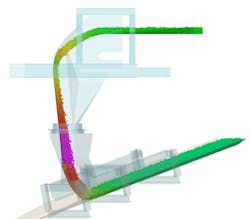
The next step in the study was to simulate the application in the pneumatic conveying system software, PneuCalc. The software was used to replicate the system parameters and ensure accuracy of the calculations. The main parameters that needed to be confirmed were the pipeline geometry, system airflow and pressure loss along the pipeline. The conveying gas flowrate needed to be carefully examined, as the system had different air injection points in the blow tanks and along the pipeline to promote dense phase conveying. The setpoint of each flow valve was recorded, and related airflow was calculated using the valve flow coefficient. The system pressure was then reviewed using the client’s historical data during operation. The software was then calibrated for the pneumatic system and material, and a graph showing the material velocity for every position in the pipeline was generated.
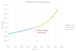
As the graph shows, the material starts to be conveyed in the pipeline in dense phase. As pressure decreases along the pipeline, the air velocity gradually increases until the material transitions to mixed phase and then to dilute phase near the end of the pipeline. The graph also shows the position of the plug in the pipeline. This position is situated in the mixed phase and probably coincides with the unstable zone of this mode. This led to the conclusion that the line plugging was caused by turbulence occurring in this transition zone. The material velocity was generally too high in the pipeline, allowing the material to exit the dense phase (but not high enough to cause material degradation).
Recommendations to solve the issue included different ways to keep the velocity under 2,000 fpm and keep the material in dense phase:
Option 1. Reduce airflow in the system, which will reduce velocity but increase pressure.
Option 2. Install an air management system to adjust airflow in-situ based on system pressure readings. This is more robust than Option 1, with a lower risk of plugging.
Option 3. Step the line to a larger diameter before the transition zone to reduce velocity and keep the material in dense phase.
The use of specialized pneumatic conveying software was a time-saver in this study and allowed the engineers to “see” the material behavior inside the pipeline. However, as previously stated, there are a few pitfalls associated with using software. The following comments are applicable to all BMH calculations and software:
- No matter the type of application, it is important to get the material properties right. In BMH, material properties are the key starting point and can swing the analysis 180 degrees. Garbage in/garbage out.
- Calibrate the calculations. Bulk materials are complicated, and the best way to gain confidence in calculations is to calibrate them on a set of parameters with a known result. In the study, the software was calibrated (for airflow, material tonnage, pipe routing, and pressure losses) using the existing pneumatic conveying system in the field. Skipping this step would have generated false results.
- Take a moment to stop and ask yourself: Do these results make sense? Judgment is key.
- If possible, benchmark the results against a similar application to increase confidence.
- Double check some outputs with manual calculations. If you can’t reproduce the results, either something is wrong, or you don’t fully understand the software approach.
- Seek training on any specific software. Learning the software’s limitations and the assumptions required to use it is very important.
Colin Barbeau is Eastern North America bulk materials handling lead at Hatch and a member of Processing’s editorial advisory board. Julien Mathieu Morel is bulk materials handling lead for Eastern Canada at Hatch.
Hatch
About the Author

Colin Barbeau
Colin Barbeau is bulk materials handling specialist at Hatch and a member of Processing’s editorial advisory board.
Julien Mathieu Morel
Bulk materials handling lead for Eastern Canada at Hatch
Julien Mathieu Morel is bulk materials handling lead for Eastern Canada at Hatch.