Where experienced engineers go wrong when designing high-velocity dust collection systems — Part 3: Fan selection mistakes
Key Highlights
- Ensure duct elbows and transitions are placed within 3 to 5 duct diameters of the fan inlet and outlet to minimize pressure losses and improve performance.
- Specify fan cold-start requirements and consider air temperature and elevation to prevent startup failures, especially in colder conditions.
- Adjust for high inlet pressures by calculating density effects to ensure the fan can handle denser air without performance issues.
- Reduce inlet duct velocity at pulse-jet collector hoppers by 20-30% to decrease abrasion, pressure loss, and improve dust distribution.
- Select the fan only after finalizing duct layout and losses, and evaluate fan curves for stable operation, power efficiency, and noise levels.
Designing high-velocity industrial dust collection systems requires a fundamentally different engineering approach than that used for conventional heating, ventilation, and air conditioning (HVAC) systems. Even experienced engineers can overlook critical factors that influence system performance and safety.
This article is the third in a series of articles highlighting the most common and costly design oversights I’ve encountered in real-world dust collection system engineering. In Part 1, I discussed useful design references, software, spreadsheets, and field-validated velocity criteria. In Part 2, I covered common duct system design errors that inhibit dust collection system performance. In this article, I’ll discuss common mistakes that inhibit system fan performance.
Ignoring fan inlet and outlet duct effects
Fan curves are typically based on standardized test configurations, with straight duct runs of 3 to 5 duct diameters at both the inlet and outlet of the fan. If duct elbows or transitions are placed within 3 to 5 duct diameters to the fan inlet or outlet, the effective loss will increase and must be included in the static pressure determinations.
On the clean side duct running from the collector outlet to the fan inlet, reduce duct velocity where feasible (around 2,000 fpm clean duct velocity is a common target) and when possible, use large-radius elbows to reduce clean duct run losses. Over the lifetime of the equipment, the added cost of a poorly designed clean air duct system can increase fan pressure requirements and lead to much higher electrical energy bills.
If layout allows, specify a dust collector manufacturer who can mount the fan directly to the clean-air plenum to reduce the pressure drop of the clean side air duct. Most manufacturers who design and build customized dust collectors for industrial facilities can mount up to a 40-hp fan onto the collector, on a platform on the side of the clean air plenum. Direct drive fans following AMCA (Air Movement and Control Association) Arrangement 5 that are 15 hp and lower can typically be mounted with a horizontal flange atop the dust collector clean air plenum.
Neglecting fan cold-start requirements
When contacting fan vendors for competitive bids on the best fan for your system’s operating flow and pressure, be sure to specify the lowest expected cold-start temperature. When fan pricing is solicited on a competitive basis, high-elevation and high-temperature systems often justify a lower horsepower drive motor, due to air density being lower. However, a lower horsepower fan that works well on hot days may be unable to start on days with colder, denser air.
It’s important to have a frank discussion with the fan manufacturer on the operation of the fan. Not just the operating temperature and elevation, but also the need to start the system up with air colder than typical operating conditions running through the fan.
Not correcting for high fan inlet pressures
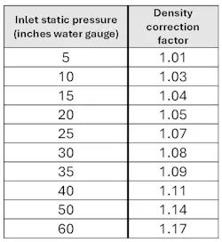
For typical dust collection systems, the system fan is drawing air into the fan inlet at a negative pressure of 8 to 15 inches water gauge. This negative pressure condition makes the inlet air denser. When the inlet fan pressure approaches or exceeds 15 inches water gauge, corrections need to be made to ensure the fan can handle this denser air at the fan inlet.
There are two methods for evaluating and adding the additional total fan pressure required to “compress” the inlet air:
- For more exact applications, you can calculate this effect by treating it as a typical density adjustment. Take the ratio of the absolute inlet pressures divided by absolute atmospheric pressure and multiply by the standard gas density to find the gas density at the inlet to the fan. Then adjust accordingly for this increased air density. Table 1 provides the results of such calculations to save you from doing the math for these density correction factors.
- For those who add extra air and pressure when selecting the fan, this extra fan inlet pressure can be added then, dependent upon the fan suction pressure requirement of your specific system.
Not reducing the hopper inlet velocity for pulse-jet collectors
As dusty air enters the dirty air inlet flange of a pulse-jet collector, it is prudent design practice to reduce the inlet duct velocity by 20% to 30% to reduce abrasion, lower flange-to-flange pressure loss, and improve dust distribution to the filter media.
For example, a 4,500-fpm duct may be reduced to a lower inlet flange velocity of about 3,800 fpm or so at the hopper inlet, while a system with a main duct velocity in the 3,000 to 3,500 fpm range may target about 2,500 fpm at the inlet. For lighter dusts with duct velocities below about 3,000 fpm, inlet expansion is often less critical.
Selecting the fan before finalizing the layout
Select the system fan only after finalizing the duct layout and all losses. Applying “similar project” fan selection typically leads to an under-performing system. When reviewing fan bids, evaluate the fan curve for:
- Stable operation well below peak static
- Operation on a steep part of the curve
- Power consumption
- Shaft speed
- Total sound emitted from the fan (including the fan body, not just inlet/outlet duct airflow noise).
Selecting the wrong fan type
I prefer backward inclined radial blade fans for most dust collection systems. I only use straight radial (paddle wheel) fans when noncombustible and nonabrasive dust is drawn through the fan and blown under pressure to a dust collection device. Straight radial fans are far less efficient than backward inclined radial blade fans and can overload if the system resistance is lower than expected.
Be aware that equipment bids containing paddle wheel fans will be inherently cheaper than bids containing proper backward inclined radial blade fans, but the systems will cost thousands of dollars more per year to operate.
Imprudent fan specification
When specifying a fan, it’s best to add 10% or more to the calculated airflow volume, depending on anticipated duct air leakage and hopper discharge device leakage. Depending on airflow and equipment selections, a 10% to 15% increase in calculated airflow is reasonable to include some air for duct leakage, rotary valve leakage and fan inlet air density.
The calculated fan pressure should also be increased by 14% to 20%. The fan manufacturer should be made aware of your design logic for the calculated flow and pressure requirements as well as the increased flow and pressure operating point with the intention of applying either a variable frequency drive (VFD) or a fan outlet damper to throttle the fan back to an operating point closer to design.
Finally, it’s prudent to increase the fan wheel speed specification by 10%. Industrial fan procurement is extremely price competitive. Fan drive components such as belts, bearings, and shafts are selected to just barely meet the rpm and power transmission requirements for the offered fan arrangement. Increasing the fan speed specification by 10% will allow plant personnel to slightly increase the air volume and pressure of the fan in the future.
In Part 4 of this article, I’ll discuss common dust collector configuration mistakes.
About the Author

Greg Black
Gregory J. Black, P.E. (Mechanical) has extensive experience in the design, application, and maintenance of industrial ventilation and dust collection systems, including applications engineering roles alongside the original patent holders for Venturi-based compressed-air filter cleaning (MikroPul) and with the Air Pollution Equipment Control Division of FLSmidth. For more than two decades he has operated Golden Eagle Technologies, LLC (Golden, Colorado), supplying equipment for granular material processing. Under the service mark, Baghouse Duct Design dot Com, he provides advisement services to plant engineers and engineering firms on industrial ventilation system design, troubleshooting, and retrofits.