Most engineers and operators involved in processing have dealt with bulk solids handling at some point and, therefore, understand that getting solids to flow in a controlled manner is much more difficult than liquid or gas streams. On many occasions, the problems with bulk solids are baked into the design, resulting in stark performance differences when compared to fluid lines. Why is that? The science underpinning bulk solid flow is dominated by frictional considerations and is different from that associated with fluids. While this difference is well established, it is generally not covered in depth in undergraduate engineering courses. As a result, many processing systems are designed with little consideration of the flowability of the material.
Beyond the lack of knowledge, bulk solid flow properties change depending on the particle size and distribution, the moisture content, temperature, time of storage, and chemical composition, just to name a few. Problems with handling solids can have a significant impact on product quality, process productivity and safety. Many bulk solids handling problems can be avoided by using a proven scientific approach based on the flow characteristics of the material. This article discusses critical design parameters required for a reliable storage vessel (such as a silo, bin, tote, intermediate bulk containers, hopper, bunker, stockpile reclaim system, self-unloading ships hull, etc.) to provide consistent feed to the downstream handling system.
Basic differences between liquid & bulk solids
Fundamentally, a bulk solid can be defined as a group of discrete particles of any size or shape in which stress is transferred between particles and the containing bin through frictional forces rather than by viscous forces. Because of this internal friction, bulk solids can form piles. Liquids are completely different because they have no internal friction and cannot form piles. Liquids are not sensitive to pressure and are incompressible, whereas the bulk density of a mass of discrete particles typically changes as a function of consolidating pressure (and particle size distribution).
Knowing the chemical makeup of a fluid allows engineers to know the flow properties as a function of temperature and pressure, whereas that is not possible with bulk solids. For example, all sugar has the same chemical, sucrose, but the flow properties of powdered sugar versus granulated sugar will be significantly different. Image 1 shows different samples of sugar.
Bulk solids include a wide range of materials that can behave differently. Fine powders, such as cornstarch, titanium dioxide and microcrystalline cellulose, may exhibit solids-gas interactions that make them prone to flooding, fluidization or a reduced feed rate. Large particles – particularly those that are irregularly shaped, such as wood chips, switch grass or wheat-midds – may form interlocking structures, or align in a bin, making discharge difficult. Some materials, such as cement, cocoa powder and fine limestone, are prone to arching or ratholing as a result of their cohesive strength. Pharmaceutical powders and glass batch blends often have a tendency to de-mix (segregate or stratify) during storage and transfer. These bulk solids follow fundamental behaviors that, when understood, can be used to design equipment that will function reliably, eliminate stagnant regions and minimize product degradation.
Flowability
The flowability of a bulk solid is a function of the material and the equipment handling it. An easy-flowing bulk solid placed in the wrong piece of equipment can become difficult to handle, but the material only appears to be hard to handle. If it is placed in the correct equipment, it can flow reliably. When working on the design of a handling system, the engineer must be aware of the material flow properties and choose the appropriate equipment for reliable flow.
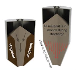
Figure 1. The two flow patterns that can occur in a bin: funnel flow (left) and mass flow(right)
Flow patterns
Material will move through a bin in one of two ways: funnel flow or mass flow (see Figure 1).
In funnel flow, an active flow channel forms above the outlet, with non-flowing material at the periphery. As the level of material in the bin decreases, layers of the non-flowing material may not slide into the flowing channel. When the bulk solid has sufficient cohesive strength, the stagnant material does not slide into the flow channel, and a stable “rathole” forms, resulting in a no-flow condition. In this stagnant region, material can gain strength over time, cake, and oxidize. It also limits the live storage capacity of the bin1 and can create cross-contamination and microbial growth issues.
In addition to flow stoppages resulting from ratholes, funnel flow can cause material degradation, results in a first-in, last-out flow sequence, and increases the extent to which sifting segregation (separation of large and small particles) impacts the uniformity of the discharging material. In these cases, the material exiting storage can be functionally different from what entered.
While funnel flow bins and silos may be problematic, problems are not a universal truth, and a large class of bulk materials is quite well-suited to being handled in these structures. These generally have the following characteristics2:
- Coarse particles – usually a quarter inch in size and larger
- Free flowing materials – composed of particles that do not stick to each other
- Non-degrading particles – materials that do not cake, spoil or oxidize when sitting for long periods of time without movement
- Segregation not a concern – either the material is non-segregating or, if it does segregate, will not affect downstream processes (for example, if operated on a batch basis)
Provided that the bulk material meets all four characteristics, a funnel flow bin is the most economical storage device. One reason is the sloping hopper walls can be shallow, which results in savings in overall headroom for the bin. In addition, by not having particles sliding along the hopper walls, no abrasive wear occurs.
However, if the four criteria above cannot be satisfied, a funnel flow pattern is no longer suitable, and a mass flow discharged pattern should be used. In mass flow, all the material is in motion whenever any is withdrawn from the hopper. Material from the center and the periphery moves toward the outlet. A mass flow discharge pattern provides a first-in, first-out flow sequence that maximizes the control of the residence time in the bin, uses the full bin capacity, and eliminates ratholing and the associated problems of the flooding of fine powders.
Mass flow bins provide other benefits over funnel flow hoppers. A mass flow discharge pattern will eliminate stagnant regions and diminish the effects of sifting segregation that may have occurred as a bin is filled. Caking, spoilage and oxidation of the bulk material is minimized because of the first-in, first-out flow pattern. Mass flow also provides a steady discharge at a consistent bulk density and a flow that is uniform and controlled. For these reasons, mass flow is advantageous for material that is cohesive, fine, will degrade over time, or in which sifting segregation is a concern.
Achieving mass flow requires:
- Sizing the bin outlet large enough to prevent arching
- Ensuring hopper walls are sufficiently smooth and steep enough to allow for the flow of the bulk solid along them
- Ensuring withdrawal of material from the entire outlet area
These requirements can be met by using a meaningful method of quantifying the properties of the bulk solid that dictate its behavior and applying the measured properties of the material as the basis for the design.
Flowability tests required for design
To design for the appropriate parameters, flowability tests need to be conducted on a representative sample of material. Key tests required are3:
- Wall friction provides mass flow hopper angles using a shear tester in accordance with American Society for Testing and Materials (ASTM) Standard D 61284.
- A cohesive strength test provides opening sizes to avoid flow stoppages caused by cohesive arching and ratholing. It is measured as a function of consolidating pressure in accordance with ASTM Standard D 6128.
- Compressibility gives the bulk density of a bulk solid as a function of consolidating pressure. It is used to determine the storage capacity of equipment and to calculate material-induced loads. It is measured in accordance with ASTM Standard D 6683.
- Permeability is the measurement of the resistance to gas flow through the bulk solid. When material contains a significant portion of fines, permeability is particularly important. The data obtained from this test are used to calculate the critical, steady-state flow rate of the material that can occur during discharge as a function of outlet size and consolidating pressure.
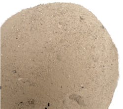
Testing conditions must match the process conditions because temperature, time at rest, moisture content, chemical composition and particle size distribution directly affect a material’s flowability, which will affect the outcome of the tests. For example, some material may be relatively free flowing at ambient temperatures, but when heated to about 1,400°F, it can sinter together (see Image 2), becoming progressively stronger at temperatures in between.
Another material may experience plugging issues with the wet material in the rainy season and dusting issues with the same material when dry unless the design has accounted for both conditions. Humidity can be a factor with hygroscopic materials during processing, storage and shipment, causing material to cake together. If material is allowed to sit in a processing bin for some period of time before discharging, then the same conditions need to be matched in the laboratory. Missing any of these conditions may cause the design data to be flawed.
Feeder below hopper
Even the most carefully designed hopper can discharge in funnel flow if the feeder does not provide uniform withdrawal of material from the entire hopper outlet. This problem frequently comes up when a gate or valve is used at a hopper outlet in an attempt to regulate flow. To use a gate to regulate flow, it must be operated partially closed. This is detrimental to reliable flow because it prevents discharge from a portion of the hopper outlet, potentially resulting in a large volume of stagnant material in the hopper.
Ultimately, a feeder should accomplish the following:5
- Provide reliable and uninterrupted flow of material from the bin above
- Control the discharge rate from a bin, achieving the required rate while preventing flooding
- Remove material from the entire cross section of the hopper outlet to avoid interfering with the mass flow in the bin above
- Seal against a gas pressure gradient (in some applications)
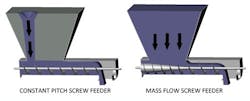
For screw or belt/apron feeders, this means the capacity must increase along the length of the hopper outlet to allow material to be activated along the entire hopper area (see Figure 2).
Conclusion
When designing a liquids processing plant, the density and viscosity of a liquid is looked up or tested and used as a design parameter. With bulk solids, the design process is similar except the friction, cohesive strength, compressibility and sometimes permeability need to be measured for the material. Many plants use a copy-and-paste technique with little consideration of the material’s flow properties.
Bulk solids handling systems are often the weakest links in the process plant, and their performance can dictate the performance of the entire operation. Therefore, they deserve special attention.
Measuring flow properties and applying them correctly will reduce project risk, potentially save a significant amount of capital and provide a peace-of-mind solution.
References
- Clement, Scott A., Paternina Gonzalez, Jairo A., and Hartford, Carrie E. “Designing Hoppers to Prevent Spoilage.” Food Technology, April 2010.
- Marinelli, J. and J. W. Carson. “Solve Solids Flow Problems in Bins, Hoppers, and Feeders.” Chemical Engineering Progress, May 1992, 22 – 28.
- Jenike, A.W., “Storage and Flow of Solids.” Bulletin 123, University of Utah Engineering Station, 1964 (revised, 1976).
- ASTM D-6128, “Standard Test Method for Shear Testing of Bulk Solids Using the Jenike Shear Cell.” ASTM International, 2006.
- Carson, J.W. “Step-by-Step Process in Selecting a Feeder.” Chemical Processing. Powder & Solids Annual, 2000, 38-41.
As a senior project engineer in Jenike & Johanson’s office in California, Carrie Hartford has been involved in troubleshooting and recommending corrective actions for material flow problems and providing recommendations to avoid material-flow-related problems in new installations worldwide in many industries – such as chemical, cement, food, biomass and mining. Typical projects include the analysis and design of transfer chutes, stockpiles, bins and feeders. From 2012 to 2014, Hartford opened and established an engineering office and laboratory facilities in Perth, Western Australia. Internationally she publishes technical papers, participates in conferences and presents numerous short courses in the field of bulk solids flow. She received her Bachelor of Science in mechanical engineering from the University of California, Santa Barbara. Subsequently, she received her MBA from Azusa Pacific University in California. Hartford is a licensed professional engineer in mechanical engineering in California. She may be reached at [email protected] or 805-541-0901.
Jenike & Johanson – http://www.jenike.com
About the Author

Carrie Hartford
Carrie Hartford, P.E., MBA, is director of business development at Jenike and Johanson. Her work involves designing bins, silos, feeders, and transfer chutes to solve challenging material handling problems for clients in all industries. She teaches courses and gives technical presentations all over the world regarding the science of material handling and storage.


