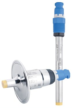
Fluid conductivity is a critical analytical measurement used in industrial processes including those found in life sciences, food and beverage, and chemical. Conductivity refers to a fluid’s ability to conduct electrical current and is used to accomplish a range of process steps such as detecting fluid interfaces, determining the quality of a process or understanding the dissolved solids concentration of a fluid.
Two-pole conductivity and inductive conductivity sensors have been available for many years, but each is limited: The first is good for measuring low conductive fluids, while the second works well with high conductive fluids. The most recent development is a four-pole sensor that measures conductivity over a much wider range.
Conductivity basics
A fluid’s ability to conduct electrical current is a result of positively and negatively charged particles present in and moving within the fluid, resulting in electrical conductance. Just as electrons move through a solid wire to conduct electrical current, current flow in a fluid is transported by ions in solution. The more free ions present, the higher the conductivity. Fewer free ions lower fluid conductivity, or inversely increase resistivity.
Fluid conductivity is measured in units of Siemens per meter (S/m). This unit of measure takes into account the amount of conductivity in the fluid across a given path length across the fluid. The commonly used cell width is 1 cm. Other common units of fluid conductivity measurement include milli-Siemens/centimeter (mS/cm) and micro-Siemens/centimeter (µS/cm). The unit of measure will change depending on the level of fluid conductivity, which varies considerably. For example, the conductivity of water can vary depending on its ionic strength.
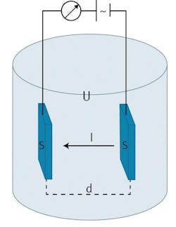
Figure 1. A conductive sensor has two electrodes, which measure the current flow across the fluid.
Pure water is actually a poor conductor of electrical current. Fluids such as deionized water (water that has been processed to remove ions) or ultrapure water (water further processed to remove trace ions) have very low ionic content; therefore, the conductivity of these fluids is extremely low. High-quality deionized water has a conductivity of around 5.5 µS/cm. Drinking water has a conductivity in the range of 5 to 50 mS/cm. A salt solution, such as seawater, can have a fluid conductivity of 5 S/m.
Some fluids have even higher conductivities because of a high level of dissolved solids. Since conductivity is a result of free ions in a solution, in many cases, conductivity can be used to correlate to the total dissolved solids in the fluid. For example, the concentration of an sodium chloride (NaCl) solution can be determined using fluid conductivity because the correlation between the NaCl concentration and conductivity is known.
Conductivity sensors measure current flow in the fluid resulting from the combination of all species in the fluid. Therefore, fluid conductivity is considered a sum parameter measurement because a conductivity sensor cannot differentiate the species in the fluid. When correlating a measured conductivity with dissolved solids, the assumption must be made that any change in conductivity is strictly caused by the dissolved solid of interest.
Fluid conductivity is also related to temperature. As the temperature of a fluid increases, the activity of the ions in the solution increases. This increase in ion activity appears as an increase in the fluid conductivity. Therefore, for a fluid of a given ionic strength, the apparent conductivity will increase with an increase in temperature. For this reason, most fluid conductivity sensors are integrated with a temperature sensor to automatically compensate for changes in temperature. Conductivity is typically standardized to 25°C. The sensor technology used to measure fluid conductivity will vary depending on the conductivity of the solution.
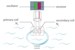
Figure 2. An inductive conductivity sensor has a primary coil generating a magnetic field that induces current flow measured by the secondary coil.
Fluid conductivity sensors
A conductivity sensor measures a fluid’s ability to conduct electrical current. Fluid conductivity is measured using one of two technologies: conductive sensors or inductive sensors. Conductive sensors are used for low-conductivity fluids, while inductive sensors are applied to high-conductivity fluids. Conductive sensors are comprised of two electrodes immersed in a liquid (see Figure 1).
The two electrodes will have a given surface area and distance between them that defines a measuring “cell constant.” Because the measured conductivity depends on the size of the electrodes and the distance between them, the cell constant defines the mechanical property of a given sensor and does not change over time.
An alternating-current (AC) voltage is applied to these two electrodes. This voltage generates a current in the fluid based on the level of free ions in the fluid. Using the cell constant and the measured current, the conductivity of the fluid is determined. The greater the number of free ions in the fluid, the greater the conductivity.
Conductive sensors cover a range from 0.05 µS/cm up to 20 mS/cm depending on the sensor’s cell constant. However, as the level of ions and conductivity increases, a point can be reached in which the number of ions interferes with the flow of current. This phenomenon is referred to as polarization, which adversely affects accuracy. At high conductivity, ions will form “clouds” at the electrode surfaces and create resistance to current flow.
This will cause a conductive probe to read an erroneously low value. The issue of polarization can be overcome by using the alternate sensor technology – an inductive sensor.
While an inductive conductivity sensor overcomes the polarization issue, this sensor technology does not have the sensitivity of a conductive sensor. Therefore, an inductive sensor is primarily used for higher-conductivity fluids, covering a range from 50 µS/cm to 2,000 mS/cm. An inductive sensor is comprised of two toroidal coils encapsulated in the sensor body, which is typically comprised of an inert plastic or polyetheretherketone (PEEK).
When a toroidal sensor is placed in the fluid, both toroidal coils share the same fluid path. The primary coil is powered with an alternating voltage to create an alternating magnetic field.
This generated magnetic field causes the ions in solution to move through the center of the sensor, producing an AC current in the secondary or sensing coil in proportion to the conductivity of the fluid (see Figure 2). The measured induced current is proportional to conductivity.
An inductive conductivity sensor has the benefits of no polarization effect, no sensitivity to fouling or the formation of a coating on the sensor, and complete galvanic isolation from the process fluid thanks to the synthetic body of the sensor.
Four-electrode sensors
Traditional, two-electrode conductivity sensors perform well in low-conductivity fluids in a range from 0.05 µS/cm up to 20 mS/cm but are limited in their upper measurement end due to polarization effects.
Inductive conductivity sensors are well suited for high-conductivity fluids in a range from 50 µS/cm to 2,000 mS/cm, but they have a limited lower range. In many processes, measurement of a broader range of conductivity is required. For example, various pharmaceutical processes need to measure the process at mid- to high-conductivity levels, requiring an inductive sensor. However, system rinsing is carried out with purewater with low conductivity, which is well below the capability of an inductive conductivity sensor.
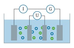
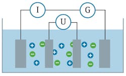
Also, a broader-range sensor in a more compact design is needed so it can be installed in smaller line sizes. Four-electrode conductivity sensors address a broader range of measurement. A four-electrode conductivity probe uses the same principles of a conductive probe but adds two additional electrodes to the sensor (see Figure 3).
Figure 3. A four-electrode conductive sensor compensates for polarization effects.
The outer two electrodes operate on the same principle as a conductive sensor in which an alternating voltage is applied to these electrodes, and the resulting current is measured. As the conductivity of the fluid increases and polarization effects begin to occur, the two additional inner electrodes measure the voltage and compensate the current measurement for any polarization effects.
This design allows a four-electrode sensor to operate across a broader measurement range than a traditional, two-electrode or toroidal sensor. The typical range of a four-electrode sensor is 1 µS/cm to 500 mS/cm. Four-pole conductivity probes can be manufactured in very compact designs. Sensors are typically available in a PG13.5, 120-mm-length geometry, similar in size to a standard pH probe.
These compact designs allow for installation in traditional holders used to install pH and other probes in a process pipe or vessel (see Image 1). In addition to the standard 120-mm size in the PG13.5 format, sensors are available with a many integral fittings such as the tri-clamp style. This design, with short sensor length, allows a sensor to be installed in small diameter pipes.
A key element in the construction of a four-electrode sensor is the secure mounting of the electrodes in the sensor head. The four metal electrodes can be stainless steel, Hastelloy or platinum. They are typically mounted in a synthetic body, such as PEEK or other plastic, to provide electrode insulation.
In sensors using metal electrodes and a synthetic body, consideration must be given to the risk of gaps occurring between the metal electrodes and the mounting substrate. Metals and plastics have dramatically different coefficients of expansion. Under extreme temperature variations, the metal pins and mounting substrate will expand and contract differently, leading to gaps between the two materials. Contaminants and bacteria can enter and be harbored in these gaps.
Endress+Hauser solved the gap problem in its four-electrode sensor by using platinum electrodes mounted in a ceramic head. These two materials have virtually identical coefficients of expansion. This design ensures that gaps do not form between the electrodes and the sensor head during temperature changes and allowed the sensor to pass strict European Hygienic Engineering & Design Group tests for cleanability, steam sterilization and bacteria tightness. This four-electrode sensor uses Memosens technology where the sensor-to-cable connection is inductively coupled. This connection eliminates all the problems associated with metal contacts such as corrosion, moisture or shorting. The connection is waterproof, and is resistant to electromagnetic interference and radio frequency interference.
Using the digital capability of the sensor, the probe also offers electrode surveillance technology to monitor the connection between the four electrodes and the sensor’s electronics. If any connections between the electrodes and the electronics fail, the sensor sends a notification to the transmitter, resulting in a diagnostic warning.
Image 1. A four-electrode conductivity sensor fits into traditional probe holders, or into fittings that allow installation into small pipes.
Summary
Fluid conductivity measurement is used across a range of industries and applications. Accurate and reliable conductivity measurement is key for the quality of many products and processes. Fluid conductivity can be measured using a conductive sensor for those fluids with low conductivity or with inductive sensors for fluids with high conductivity.
Today, four-electrode conductivity sensors are available to span a greater range than two-electrode sensors and are available in more compact designs. These sensors are well-suited for applications in many processes, virtually anywhere a broad range or compact design is required.
Steven Smith is the senior product marketing manager – analytical for Endress+Hauser USA. He is responsible for technology application, business development and product management over a wide range of analytical products. He has a bachelor’s degree from the University of Wisconsin and an MBA from the University of Colorado. Smith has spent the past 25 years working in process instrumentation and control with industry-leading Fortune 500 companies.
