Specifying thermal management systems for control enclosures
Most electrical control devices must be housed in a control enclosure when used in industrial environments. This includes controllers, drives, power supplies, disconnects, fuses, terminals, relays, contactors and more. Not only does the enclosure protect the devices from dirt, debris, oil and other liquids, it also protects plant personnel from hazardous voltages. The warm environment on the plant floor and heat generated by electrical devices can create the need to cool the enclosure. If the enclosure is mounted outside, it may be necessary to heat the enclosure to protect the devices from extreme cold.
Changing temperatures in the plant or outside may demand use of both cooling and heating to maintain an optimal temperature. Controlling the temperature can eliminate the risk of condensation forming inside the enclosure, and eliminate overheating or freezing of the electrical devices.
Different types of thermal management systems are used to control the temperature and other conditions inside control enclosures. An overview of how to specify these systems — including venting devices, air conditioners, vortex coolers, heat exchangers and heaters — is discussed in this article to help ensure cost-effective and efficient control of an enclosure’s internal environment.
Optimal enclosure temperature
Heat is transferred into or out of an enclosure to control the internal temperature using conduction, convection and/or radiation. Conduction is heat flow through the enclosure wall or other solid materials. Convection is heat flow through a moving fluid or gas, or a moving fluid to the surface of a solid. Radiation is the transfer of thermal energy using electrical energy such as a strip heater.
Since most electronic components perform better and last longer when operated at lower temperatures, heaters are not often used to keep internal components warm unless installed in areas where ambient temperatures dip well below freezing. In this case, heating is needed to stay within the operating range of the internal electrical components.
Heating, however, is often needed to reduce the humidity and its consequences, namely condensation, that can cause corrosion. A heater can keep the relative humidity below 65 percent to prevent condensation. Mounting the heater near the bottom of the enclosure is optimal for natural convection, and larger heaters — typically over 150 watts (W) — often include a fan to help distribute the radiated heat evenly throughout the enclosure.
This article will focus on the cooling of a control enclosure, which is needed in many applications.
A cool control enclosure
The need to cool a control enclosure is common because natural conduction from the exterior is often not sufficient to keep the internal temperature within an acceptable range. Excess heat is produced by internal devices such as transformers, drives and power supplies. High external temperatures are often also present, either due to weather conditions or to heat generated by equipment such as ovens or furnaces. Too much heat reduces the operating life of electronic hardware such as controllers, drives, computers and displays. Excess heat can also require derating of power supplies, change circuit protection performance or trip an overload.
Internal and external factors affect an enclosure heat load. Ambient temperature has a large effect as heat flows from a higher temperature to a lower temperature. High ambient temperatures often create the need to cool an enclosure.
An enclosure can also seal in heat produced internally if it is not properly vented. Other cooling methods can be used if ambient venting while keeping contaminants out is not possible, or if venting is not sufficient.
Common enclosure cooling methods include natural convection, forced convection and closed-loop (see Figure 1). Vortex cooling, which generates a stream of cold air using compressed air, is another enclosure cooling method.
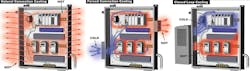
Figure 1. Common enclosure cooling methods include natural convection, forced convection and closed-loop.
Natural and forced convection
Convection is often the only method used to control the temperature inside a control enclosure. Air movement has a large effect on the rate of convection; the more air movement inside the enclosure, the better the heat transfer rate. Natural convection, caused by hot air rising, can circulate the air in a control enclosure and keep it cool. Forced convection adds a fan to improve heat-transfer rates. For natural and forced convection to be effective, an ambient temperature cooler than inside the enclosure is required.
If minimal cooling is needed, natural convection using two grills or louver plates with filters is a common solution. With proper installation, hot air exits the top of the enclosure due to convection, drawing in cool air at the bottom of the enclosure. In applications where the environmental rating needs to be maintained and the enclosure needs to be sealed, breather vents and breather drains can be used.
Forced convection provides better heat removal by using a fan to provide a constant air flow through the enclosure (see Figure 2). Typically, a fan and filter are mounted low in the enclosure to force moderately cool ambient air into the enclosure. An exhaust grill and filter installed high in the enclosure allows the hot air to be forced out. This forced convection can protect devices from overheating and eliminate localized heat pockets. Additional compact fans, mounted on the control enclosure back panel, can provide spot cooling with focused air, if required.
Natural and forced air convection cooling does not always get the job done and, in these situations, closed-loop cooling is required.
A closed cooling loop
Closed-loop cooling is used where there is a high heat load from internal components and/or where there is a high ambient temperature. It is also used to maintain a safe temperature level for internal devices without adding outside air to the enclosure. Closed-loop cooling is often specified for control enclosures because of the following reasons:
- High ambient temperatures
- Internal components generating excessive heat
- Harsh environments
- Washdown areas
- Heavy dust and debris
- Airborne corrosive or chemicals vapors
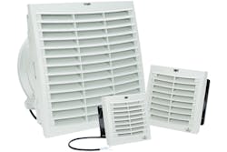
Figure 2. These Stego filter fan assemblies from AutomationDirect provide forced air convection in an enclosure, providing better heat removal than natural convection due to constant forced air flow.
Many closed-loop cooling options maintain the enclosure protection rating, including air-to-air heat exchangers and air conditioners. An air-to-air heat exchanger does not require refrigerant, but its cooling capacity is limited.
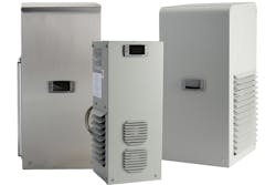
An air conditioner provides more cooling capacity due to the addition of a refrigerant, an evaporator and a condenser (see top photo). Although the compressor uses much more electrical energy than a fan or heat exchanger, proper use of enclosure thermal management controls and high-efficiency compressors reduce these costs.
A refrigerant-free vortex cooler is another option when isolation from ambient air is required. Although technically not a closed-loop system, since the cold air is created using a filtered compressed air source, the National Electrical Manufacturers Association (NEMA) enclosure rating is maintained.
Like an air conditioner, a vortex cooler is effective under high ambient temperature conditions. The air usage of a vortex cooler must be considered in its operating cost, but it is inexpensive to purchase and install, and it requires no maintenance.
Basics of sizing cooling solutions
In addition to choosing the appropriate natural convection, forced convection or closed-loop cooling method, the size/capacity of the cooling device must be calculated.
Enclosure fan sizing: To calculate the minimum fan cubic feet per minute (CFM) for a forced air cooling solution, determine the amount of heat to be removed (watts) and the maximum temperature differential (∆T).
Cubic feet per minute (CFM) = (3.17 x P) / ∆T °F
Where: P = Power to be dissipated in watts
∆T = (max outside ambient air °F) – (max. allowable internal enclosure air °F)
The air constant (3.17 in the above example) is determined by the altitude above sea level where the enclosure is installed. To simplify the calculations for the volume flow required, vendors provide online help, such as a cooling calculation tool.
Air conditioner or vortex cooler sizing: When calculating proper unit size, worse-case conditions should be used, which eliminates the need to oversize. Two key factors in the cooling calculation are internal heat load and heat load transfer.
The internal heat load is the heat generated by the electrical devices inside the control enclosure. A favored way to determine this is to add each device’s maximum heat output specification (watt-loss). The values are usually given in watts and will need to be in British thermal units (BTU) for cooling capacity calculations. Watts are converted to BTU as follows:
BTU per hour (BTU/H) = Watts x 3.413
The heat load transfer is the heat lost or gained through the enclosure walls to the surrounding ambient air and is calculated using the following formula:
Heat load transfer (BTU/H) = 1.25 x surface area (ft2) x (max. outside ambient air °F – max. allowable internal enclosure air °F)
Note: 1.25 is an industry standard constant for metal enclosures; for plastic enclosures it is 0.62.
Surface area (ft2) = 2 [(H x W) + (H x D) + (W x D)] / 144 square inches
Once the internal heat load and the heat load transfer are determined, the cooling capacity required is calculated as follows:
Cooling capacity (BTU/H) = Internal heat load ± Heat load transfer
Be sure to understand whether the enclosure needs to be kept cool, warm or both. Once the cooling and heating system needs and methods are defined for an application, the solution must be properly sized and then the proper system selected.