When and when not to use thermowells in process temperature measurement

Within the world of process instrumentation, temperature measurement presents unique challenges due to the need for a thermowell to protect the temperature measurement sensor from harsh process conditions. This results in the sensor being removed from the process it is supposed to be measuring, often impacting response time and accuracy.
A resistance temperature detector (RTD) is most commonly constructed from a platinum element with leads attached, which is encased in a stainless-steel sheath to protect it mechanically and electrically. A thermocouple is usually more mechanically robust, but still requires a high degree of protection. In either case, heat from the process must flow through the protective components and any internal insulation to reach an equilibrium temperature between the sensor and surrounding process.
This heat flow takes time and creates a lag between an actual process temperature change and the point when it is recognized by the automation system. The relatively small enclosure of the sensor itself, typically 5 to 7 mm in diameter, is rarely installed such that it sees direct process contact. Most processes use a thermowell (see Figure 1) to isolate the sensor assembly so it can be extended into the process without direct contact.
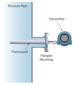
A thermowell mounts through a vessel or pipe wall to extend into the process fluid to the desired temperature measurement point (see Figure 2). The sensor is inserted into the thermowell from outside the process so it can be accessed without requiring a shutdown. The thermowell is exposed to the process fluid, so heat transfers through its wall and eventually conducts to the sheath and sensor itself. Equilibrium is eventually reached, and the sensor then provides a reading representative of the process fluid temperature.
If the process fluid temperature changes, the new temperature must make its way through all those layers. Depending on the application, this can take a few seconds to several minutes. Few processes experience sudden temperature step changes, so this arrangement is adequate for most real-world applications.
The tradeoffs of thermowell selection
The process engineer will often specify where a temperature reading needs to be taken. For example, the sensor needs to be placed in the pipe coming out of a reactor, and the reading taken from the center of the pipe. Therefore, the thermowell insertion length needs to be half the internal diameter of the pipe.
The process engineer will also determine how much and how quickly the temperature is likely to change in normal operation, and how quickly the measurement point needs to be able to communicate a change to the automation system. If the movement needs to be recognized in a very short time, the thermowell will need thin walls to conduct heat quickly to the sensor.
At the same time, the walls must be thick enough to withstand any mechanical stresses and pressures without distorting or failing. Naturally, the thermowell must be made from an appropriate material able to withstand the chemical and temperature environment, usually the same material as the pipe or vessel where it is inserted.
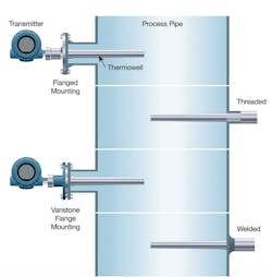
The thermowell installer will choose a connection method to fit the situation from one of four common options (see Figure 3):
- Threaded thermowells are threaded into the process piping or a vessel, which allows for easy installation and removal when necessary. While this is the most common method of mounting, it has the lowest pressure rating, and threaded connections are prone to leakage.
- Welded thermowells are permanently welded to process pipes or vessels and used in applications with high-velocity flow, high temperature and/or high pressure. While reliable and leak-resistant, removal is difficult and requires cutting the thermowell out of the system.
- Flanged thermowells are bolted to a mating flange, or spud welded onto a process pipe or vessel. They are used in applications with corrosive environments, high fluid velocity, high temperatures and/or high pressure.
- Van Stone or lap-joint thermowells are mounted between a mating flange and the lap-joint flange. These thermowells allow use of different materials for the thermowell coming in contact with the process and for the overlaying flange, which can save material and manufacturing costs.
Fluid flow is the biggest challenge
If a correctly specified and installed thermowell is located where the fluid is largely static, such as in some vessels, it can have a long service life. Problems arise when a thermowell is inserted in moving fluid, which is the most common type of application. The thermowell is normally mounted perpendicular to the flow, so the fluid hits it broadside. It, therefore, creates a partial obstruction and causes a drag on the fluid.
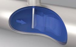
Figure 4. This model illustrates how vortices detach from the thermowell.
As the fluid flows past a round thermowell, high- and low-pressure vortices form at both sides. These vortices detach, first from one side and then from the other, in an alternating pattern (see Figure 4). This phenomenon is commonly known as vortex shedding. The differential pressure caused by the alternating vortices produces vortex-induced vibration (VIV), resulting in stresses and causing transverse and axial deflection, which can ultimately lead to fracture. It is as if the thermowell is being pulled up and down perpendicular to the flow.
The frequency of the oscillations is referred to as the wake frequency and is affected by the fluid velocity. It is not a linear relationship, so the vibration does not necessarily increase with an increase in velocity. As fluid velocity changes, VIV will increase and recede at various points, so there are conditions where an installation can run relatively safely.
The worst situation takes place when the wake frequency corresponds to the natural frequency of the thermowell, producing potentially violent VIV. If the dynamic stresses exceed the maximum allowable working stress limits of the thermocouple, it will succumb to fatigue and fail. Thermowell manufacturers should provide thermowell calculations to predict the probability of a thermowell failing. The American Society of Mechanical Engineers (ASME) provides a method for calculating the dimensions necessary for a thermowell to be strong enough to operate satisfactorily in a given application here.
Such calculations depend on a single set of static process conditions, which is not the case in most real-world situations. The conventional solution is to make thermowells as short as the process can accept and as thick as can be inserted, but this increases the time lag for capturing a temperature change and can impact accuracy. The alternative is to find a profile able to suppress VIV formation.
Modifying thermowell geometry to reduce VIV
Cylindrical, stepped and tapered thermowells are all basically round – so they have similar VIV characteristics, allowing vortices to form along the entire length. A new design (see Figure 5) disrupts formation of the long vortices and allows them to form on both sides, so they tend to balance and cancel each other. The result is far less VIV, up to a 90 percent reduction in some cases.
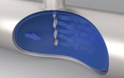
Figure 5. Emerson’s new and patented Twisted Square thermowell breaks up normal shedding characteristics and reduces mechanical stress.
Helical geometry like this has been used successfully with wind stacks and deepsea risers to solve similar problems. It does not depend on a specific orientation when inserted, and reduces the need for excessively thick thermowells and large diameter process penetrations. Moreover, it is effective and suitable across a wide range of operating parameters.
Inferring process temperature from a surface temperature reading
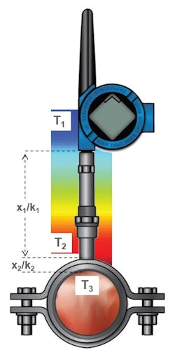
Figure 6. A sophisticated series of calculations available in new technology makes the surface reading match the process temperature very closely.
Since all temperature readings depend on the heat conductivity of the thermowell and sensor sheath, why not mount the sensor on the outside of a pipe and infer the process temperature from the amount of heat transferred through the wall? This eliminates the need for a thermowell, and provides an accurate reading if appropriate adjustments are taken:
- A surface reading will reflect the fluid near the outside wall, which may not be the same as the center of the pipe.
- Thermal conductivity characteristics of the pipe, including material and thickness, must be taken into consideration.
- Ambient temperature conditions must be included in the calculation.
If the sensor can be placed in solid, direct contact with the pipe wall and thoroughly insulated, a usable reading can sometimes be inferred from the sensor output. However, changing ambient temperature conditions will substantially affect the accuracy of the reading, leading to a search for a better solution.
New technology (see Figure 6) is designed to measure surface temperature, and corrects and compensates for heat transfer and ambient condition effects resulting in an accurate process temperature measurement without requiring any intrusions or penetrations into the process. The unit is installed using a simple pipe clamp assembly and then insulated. The pipe material and wall thickness are entered into the transmitter so it can calculate heat flow and extrapolate the process temperature inside the pipe. The unit also uses an ambient temperature reading taken inside the transmitter enclosure to account for changing ambient conditions.
This approach has a variety of advantages:
- It can be installed without a process penetration, so no shutdown is necessary.
- It can be used where pipe diameters are too small for a thermowell.
- Since no parts are wetted, there is no need for exotic materials.
- The assembly can be moved to a different measuring point if necessary.
- Wired and wireless options make installation easy.
Like any surface temperature measurement, the new technology is subject to the same time lag and near-the-inside-wall reading characteristics, however the advantages often outweigh these limitations. Any temperature measuring application will be a compromise, but the growing number of options now available make selection much easier.

Ryan Leino is the Rosemount Temperature Global Product Manager for Emerson in Minnesota. He holds a bachelor’s degree in chemical engineering from the University of Wisconsin-Madison. Leino has 11 years of experience with Emerson in the areas of inside sales, product marketing and product management. Connect with him on LinkedIn at http://www.linkedin.com/in/ryan-leino-256a8523.