Thermoplastic valves: Selection & actuation
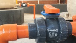
Thermoplastic valves have the advantage of being lightweight, corrosion resistant, chemical resistant and non-toxic. They also will not scale or rust and have low thermal conductivity. Commonly used in municipal and industrial chemical feed systems, thermoplastic material is rugged and well-proven for industrial applications when used within the range of the material’s specifications. Thermoplastic valves fitted with electric or pneumatic actuators also allow for automated control and remote access by operators.
Thermoplastic valve materials
The most common materials used in thermoplastic valve manufacturing are PVC, CPVC, GFPP and PVDF. Each of these materials has inherent properties defined by their individual cell classification codes outlined by ASTM standards. Cell class codes define the material, impact resistance, tensile strength, elasticity and heat deflection temperature. Schedule 80 PCV ball valves manufactured for industrial applications, for example, meet ASTM D1784 Cell Class 12454, whereas a GFPP ball valve meets ASTM D4101 Cell Class 85580. Both materials inherently perform differently at the same operating temperature, pressure, impact and UV exposure.
The thermoplastic valve body is precision molded from the base material. Thermoplastic valve assemblies additionally have smaller components made of different material that also interact with the liquid process. All of these materials require careful attention during valve selection due to potential chemical compatibility. Incorrect material selection, especially of O-rings and liners, can lead to premature valve failure.
Ball valves use elastomer O-rings made of EPDM or FMP. These are located in the end connections and stem to create a sealing surface between plastic components. PTFE seats on either side of the ball provide a smooth travel and sealing surface for the ball to ride and seat against. Thermoplastic butterfly valves have an elastomer liner that the disc seals into and O-rings made of EPDM, Viton or Nitrile. A thermoplastic butterfly valve also has a stainless steel or titanium shaft that holds the liner and disc assembly in place within the valve body.
When specifying a valve for a potentially corrosive application, consulting a chemical resistance chart for the thermoplastic and elastomer material chemical compatibility will ensure correct material selection. EPDM rubber is an elastomer recommended for water, steam, dilute acids, dilute alkalis and alcohols.
FPM or FKM is a fluorocarbon rubber recommended for petroleum oils, diester base lubricants, silicate fluids and greases, halogenated hydrocarbons, acids and vacuum environments. PTFE is chemically stable and virtually unaffected by chemicals, acids, bases and solvents.
All thermoplastic material operating pressure decreases as temperature increases. Maximum operating pressure of a 2-inch ball valve can be 250 psi at 70°F, non-shock. The pressure and temperature curves are different for PVC and CPVC. The same schedule 80 PVC ball valve will have a max pressure of 130 psi at 145°F.
Flow velocity
Thermoplastic piping systems are intended for flow rates between 5-8 feet per second (FPS). When velocities climb higher than 8 FPS, water hammer can result, damaging system components. High velocities also put additional load on valve components and actuators as they cycle open or closed. Consulting a flow velocity chart can assist with proper sizing.
Selecting a valve
In general, thermoplastic ball valves are either full-port or characterized port. Full-port ball valves are intended for full-flow or shut-off but not for throttling. Fluid velocities within the valve change radically as a valve moves from full open to a closed position. The high velocities passing through a partially open full port can erode the trim on the ball and the PTFE seat. Using a characterized port ball valve would be recommended for manual throttling or proportional control with an actuator.
Butterfly valves are intended for both open/close and throttling/proportional control. The design of the valve’s concentric disc and thick elastomer liner allow for valve operation through the entire 90-degree travel range.
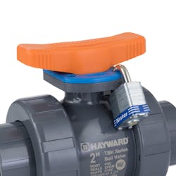
Ball valve and butterfly valve handle and lever design should allow for easy lock placement to achieve Lockout/Tagout (LOTO). LOTO is a critical safety procedure used by individuals performing maintenance on a piping system, preventing a valve position change while system maintenance is being performed. Hayward’s TBH Series ball valve handle lockplate design, for instance, makes accomplishing LOTO fast and easy.
With the drive for more automation in the industrial markets, more manual valves are being converted to actuated valves. The two most common thermoplastic valve types that can be converted from are ball valves and butterfly valves. Both valves are rotary, turning 90 degrees open to closed. An exception to this are some three-way ball valves that may have a 180-degree rotary motion, depending on the type of internal ball.
When considering an actuation option, the following questions need to be addressed:
- Does the valve body have an actuator mounting flange, or will special adaption hardware be required?
- Does the valve stem allow for direct coupling with an actuator, or will a stem adaptor be needed?
- Does the flange bolt pattern match the actuator housing bolt patter, or will an adaptor be needed?
- What are the valve stem dimensions compared to the actuator drive socket dimensions (i.e., a round keyed valve shaft and square drive actuator socket)?
- Who will be doing the valve and actuator assembly, and how will that affect field support and potential warranty issues?
When selecting an actuator, valve torque requirements and actuator torque output are top considerations. Valve type, size and required safety factor determine the torque rating of a valve. As an example, the ball inside of a thermoplastic ball valve rotates against smooth PTFE seats. A large 6-inch ball valve has a torque rating of 170 in/lb force (due to the safety factor accounting for full system flow and pressure), so a relatively compact actuator can be mounted on a large valve. Comparatively, butterfly valves have higher actuator torque requirements due to the valve disc interacting with the rubber liner during rotation into or out of the closed position. Sizing an actuator correctly will ensure ample torque output to efficiently and safely operate a valve even under peak flow and pressure conditions.
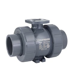
ISO 5211 is an international standard that defines the actuator mounting dimensions and drive square size. Valves that are designed with an ISO 5211 actuator mounting flange will more easily and securely accept an actuator manufactured with an ISO 5211-compliant housing. Hayward Flow Control’s BYV Series butterfly valve and TBH Series ball valve, for example, have fully molded ISO 5211 flanges. Hayward actuators are also ISO 5211 compliant.
Even with an ISO 5211 valve flange and compliant actuator, coupling the valve and actuator may require a stem adaptor. The plastic stem of a ball valve will require a transition piece to the metal actuator drive socket. The coupling piece and any additional bracketry will be determined by the valve size and stem design.
Butterfly valves have a metal shaft that secures the disc and liner into the valve body and protrudes above the valve flange, providing a means of handle or actuator attachment. Depending on the valve size, the valve stem my be square or round. A square stem may allow for direct actuator mounting if the drive socket matches the stem dimensions. A round stem would require a shaft adaptor and additional mounting bracket to couple with a square-drive or double-square drive socket.
There are many variables and iterations when considering valve actuation. Working closely with the valve and actuator manufacturer will ensure a well-operating assembly that is fully covered under the manufacturer’s warrant.
Electric & pneumatic actuators
When considering actuating a thermoplastic valve, the following points need to be identified:
- Valve type: ball, butterfly, diaphragm, three-way ball
- Valve size
- Valve operation: on/off, throttling (modulating 4-20 mA), 3-position
- Installation: indoors or outdoors
- Electric or pneumatic
Additionally, options when selecting an electric actuator include voltage (AC or DC), positioner (4-20 mA), handwheel, battery backup, auxiliary limit switches, local control station, torque switches, submersible housing and explosion-proof housing.
Pneumatic actuators require plant-supplied air and come as either double-acting or spring return. Options include solenoid (AC or DC), air filter/regulator, positioner (4-20 mA), auxiliary limit switches, visual indicator and declutchable manual override.
Actuator cycle time is the time it takes an actuator to travel from open to close and is important for preventing water hammer resulting from a valve opening or closing too fast. The cycle time of Hayward’s HRSN2 electric actuator for a 4-inch ball valve is approximately 9 to 13 seconds. Cycle time for a 12-inch butterfly valve is approximately 39 seconds. For electric actuators, this speed is fixed.
Speed of a pneumatic actuator is governed by a solenoid assembly that opens or closes on command and regulates the flow of air into and out of the actuator piston cylinder. Double-acting actuators have air supplied to both the open and close cylinders. On loss of supply air, a double-acting valve will remain in the last position. Fail-safe spring return actuators are used in applications that require a valve to travel to either a full-open or full-close position in the event of loss of air supply. The fail-safe position is selected when specifying the actuator but can be changed in the field, if needed.
Actuator duty cycle
Electric actuators have a run-time/rest-time ratio called duty cycle. Actuators give off unused energy as heat, which can damage actuator components. An actuator with a 25% duty cycle will need three times the rest time as the run time to allow the heat to dissipate. In other words, an actuator has full travel cycle time of 9 seconds, it will need 27 seconds of idle time before it should cycle again. Valves requiring proportional control that are continuously modulating will need an actuator with a duty cycle of 75% to 100%.
Local control stations
An actuator operates based on a command given by a control system, such as a PLC or SCADA. The actuator is sent a signal to go open or closed, and the actuator motor turns the ball or disc until at the end of the travel rotation; contact is made with an end of travel switch. This function is performed in a remote area that may be a significant distance from the actual location of the actuated valve.
Local control stations (LCS) give the option of performing this function right at the actuator. The LCS is included as part of the actuator design. A selector switch on the LCS allows the operator to switch control from the “remote” control room to the “local” site of the installation. An operator is then able to use an open/close switch to drive the valve to the desired position.
LCS options can be a key/knob type, which only have an IP65 environmental rating and are not suited to washdown situations, or a full LCD display type with an IP67 environmental rating, and visual display of valve travel position and diagnostics.
Explosion-proof requirement
Installations are often located in hazardous locations that may have flammable gases periodically or continuously present and require electrical equipment with explosion-proof ratings. In a hazardous location, it is assumed that the atmosphere inside of an actuator enclosure is the same as the hazardous atmosphere outside. If there are flammable gases potentially present, the actuator housing design has to be able to withstand the internal compressive forces of combustion and contain any flame or spark inside of the actuator housing. This design requirement applies to the housing, power and signal connection points, and any mechanical coupling points to the valve. Actuators with an explosion-proof certification will carry an EX rating on the housing.
Conclusion
For engineers, contractors and operator/owners, working closely with a manufacturer that specializes in thermoplastic valve actuation can help navigate the list of requirements and options available during the selection process. Manufacturers that provide complete valve and actuator assembly and testing in-house are positioned to provide superior pre-purchase technical support, field support and warranty coverage. As valve and actuation technology advances, manufacturers with a strong drive for product development and industry leadership will continue to deliver products that meet the critical needs of the process industries.
Wes Murray is the district sales manager for Hayward Flow Control, responsible for the Desert Southwest, USA territory. Since 2004, his technical sales experience has been centered in the industrial markets of oil and gas, water and wastewater treatment, power generation, chemical and municipal water and wastewater treatment. His current industry involvement with Hayward Flow Control also include data centers and semiconductor plants. Murray received a B.S. in horticulture from Utah State University.
Hayward Flow Control
About the Author
Wes Murray
Wes Murray is the district sales manager for Hayward Flow Control, responsible for the Desert Southwest, USA territory. Since 2004, his technical sales experience has been centered in the industrial markets of oil and gas, water and wastewater treatment, power generation, chemical and municipal water and wastewater treatment. His current industry involvement with Hayward Flow Control also include data centers and semiconductor plants. Murray received a B.S. in horticulture from Utah State University.