Where experienced engineers go wrong when designing high-velocity dust collection systems — Part 4: Dust collector configuration mistakes
Key Highlights
- Implement vibration isolation for fans, ducting, and process equipment to prevent structural damage and maintain system integrity.
- Use flexible hoses sparingly, primarily for short, final connections, and prefer smooth-wall static conductive hoses to minimize pressure losses.
- Consider high side inlet configurations for abrasive or fine dusts to reduce turbulence, pressure drop, and extend filter life.
- Evaluate bid proposals carefully by analyzing can velocity and interstitial velocity to avoid high velocities that can impair system performance.
- Avoid returning collected dust onto conveyors upstream of other collection points to prevent re-entrainment and system clogging.
Designing high-velocity industrial dust collection systems requires a fundamentally different engineering approach than that used for conventional heating, ventilation, and air conditioning (HVAC) systems. Even experienced engineers can overlook critical factors that influence system performance and safety.
This article is the fourth in a series of articles highlighting the most common and costly design oversights I’ve encountered in real-world dust collection system engineering. In Part 1, I discussed useful design references, software, spreadsheets, and field-validated velocity criteria. In Part 2, I covered common duct system design errors that inhibit dust collection system performance. In Part 3, I discussed common mistakes that inhibit system fan performance. In this article, I’ll describe common dust collector configuration mistakes.
Failing to provide vibration isolation
Fans, ducting and process equipment create and carry vibrations. Providing isolation is critical to protect structures and keep mechanical connections intact.
Fan manufacturers can provide flex connectors for the fan inlet duct, or some end users fabricate their own by cutting a section of duct and wrapping and band clamping rubber sheeting over the gap. Ducting can also be purchased with vibration isolation sections.
The easiest way to isolate machinery vibrations from the duct system is at collection points, applying a very short run of flexible duct between the metallic duct terminus and the duct system collection point, affixed with hose clamps.
Consider vibration isolation for the fan base when mounting to structural steel or the dust collector. Confirm fan vibration isolation requirements with the fan manufacturer.
Overusing flexible hose
Use flexible hose primarily for short final connections for vibration isolation and final fitment. Smooth-wall static conductive hose is best. Hose with an internal helical-wire 'bumpy' wall, can impose extreme losses, especially when compressed. One flexible hose manufacturer’s guidance indicates that compressing a run of 4-inch hose by 20% can increase pressure drop by about 8 times compared to smooth metal duct.
Keep hose short, routed with long-radius bends, and as fully extended as practical. Consult the hose supplier for loss data if hose length is significant.
Not using a high side dust collector inlet
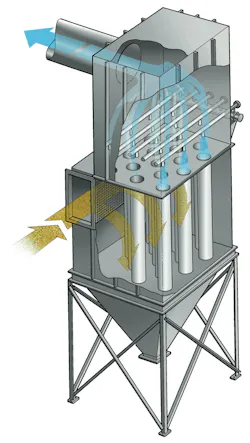
For abrasive, sticky or extremely fine dusts, consider relocating the dirty air inlet to the dust collector from the hopper to a high side configuration (Figure 1). A high side inlet is located high up on the housing just below the tube sheet, eliminating ‘can velocity’ considerations and providing for a quiet hopper zone where the dust can settle.
A high side inlet decelerates the incoming dusty air as it enters the collector, allowing gravity to draw the dust into a quiet hopper, while the remaining dirty air moves laterally toward the filters. This can reduce turbulence, lower flange-to-flange pressure drop, reduce pulsing frequency, and extend filter life. When retrofitting an existing dust collector containing excess media area, some rows of filter bags can be removed to create the inlet void space.
Failing to include can velocity and interstitial velocity when evaluating dust collection device competitive bids
The dust collection industry is very competitive. Equipment suppliers will typically propose equipment that will meet the process specifications at a price that’s in the lower range of bid offerings. Some dust collector application engineers may respond by offering equipment with pleated cartridge filters that have the same basic dimensions as standard bag filters but provide more filtration area in the same equipment footprint. Some application engineers may see a price benefit by specifying fewer but longer bag filters that fit into a taller and skinnier dust collector. Either of these actions can result in very high can velocities and cause problems with the system.
The generic fabric filter dust collector design is a Venturi compressed-air cleaned dust collector based on the 1950s MikroPul design, with the dirty air inlet placed within the hopper, just above the rotary valve. With this configuration, the air flows upward, carrying the dust up into the bag filters. When a row of filters is pulsed, the dust is expected to fall downward through the upward flowing air. With such hopper inlet designs, the collector footprint and filter media area are evaluated to consider both the can velocity (upward airflow velocity through the collector housing) and the interstitial velocity (upward airflow velocity in between the bag filters, calculated at the bottom plane of the bags).
Industrial Ventilation: A Manual of Recommended Practice for Design, 31 Ed. (Figure 8-9, pg 8-19) provides some guidelines of acceptable interstitial velocities based on bulk density. This serves as a guideline to evaluate competitive bids, particularly when considering tall collectors with long filter bags.
Returning collected dust to the process
Avoid discharging collected dust onto a conveyor upstream of another dust collection point on the same conveyor and dust collection system. The downstream hood can re-entrain the fines and recirculate them back into the dust collection system.
Eventually this ultrafine dust builds up within the collector housing, remaining forever aerated by the upward flow of air in the collector. This buildup of dust within the collector housing will eventually choke the collector with fines, increase collector pressure drop, shorten filter life, and create a large dust release when the system is shut down.
If dust must be returned to the belt, know that such systems will periodically need to be shut down to purge the system of ultra fine dust. Such purging will require fan flow shut down, to either mechanically vacuum out the fine dust from the collector or accept a dusty mess while the conveying system and dust collector rotary discharge valves are run until the dust collector hopper is empty.
In Part 5 of this article, I’ll discuss silo bin vent systems.
About the Author

Greg Black
Gregory J. Black, P.E. (Mechanical) has extensive experience in the design, application, and maintenance of industrial ventilation and dust collection systems, including applications engineering roles alongside the original patent holders for Venturi-based compressed-air filter cleaning (MikroPul) and with the Air Pollution Equipment Control Division of FLSmidth. For more than two decades he has operated Golden Eagle Technologies, LLC (Golden, Colorado), supplying equipment for granular material processing. Under the service mark, Baghouse Duct Design dot Com, he provides advisement services to plant engineers and engineering firms on industrial ventilation system design, troubleshooting, and retrofits.