Cavitation control in industrial piping systems
Key Highlights
- Cavitation occurs when local static pressure drops below vapor pressure, causing vapor bubble formation and collapse, which can damage piping and supports.
- Restriction orifice plates can induce cavitation by creating high velocity flow and significant pressure drops, especially at the vena contracta downstream of the restriction.
- Differentiating between cavitation and water hammer is crucial; cavitation produces continuous noise and vibration, while water hammer results from transient pressure waves during rapid flow changes.
- Multi-stage restriction assemblies distribute pressure drops across several stages, reducing cavitation severity but increasing system length and complexity.
- Engineered single-stage anti-cavitation flow paths can manage vapor bubble development within the restriction geometry, offering an alternative to multi-stage solutions.
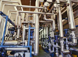
Your phone rings. A technician is standing near a 14-inch cooling-water line that is shaking so violently during a heat exchanger backflush procedure that he is concerned the Schedule 40 piping or its supports could fail.
He says it has happened before. The vibration begins when the backflush starts and stops almost as quickly when the procedure is complete. Once the piping becomes quiet again, the concern fades and the rest of the day’s work takes priority.
During the backflush operation, most of the system flow is diverted through a bypass line containing a restriction orifice plate. At first, attention may turn toward the heat exchanger. Perhaps reverse flow is creating an unstable condition. With relatively few components in the bypass circuit, it may be hard to imagine that a simple flat restriction orifice plate could be the source of such violent vibration.
But in this case, the restriction was exactly where the problem originated.
The plate was taking a substantial pressure drop while passing a high liquid flow rate. As the fluid accelerated through the restriction, the local pressure dropped low enough for cavitation to develop downstream of the plate.
The result was noise, vibration and mechanical stress severe enough to make the piping system appear as though it might shake itself apart.
What is really going on?
Cavitation is commonly associated with pumps, but pumps are only one place where it can occur. Any component that creates a sufficient localized reduction in liquid pressure can potentially create cavitating conditions, including restriction orifice plates, control valves and partially closed valves.
In a restriction orifice application, the liquid accelerates as it passes through the reduced flow area. As velocity increases, local static pressure decreases. The minimum pressure typically occurs near the vena contracta, just downstream of the restriction.
If the local static pressure falls below the liquid’s vapor pressure at the operating temperature, vapor bubbles begin to form.
As the liquid continues downstream and pressure begins to recover, those vapor cavities rapidly collapse. Bubble collapse can generate localized pressure pulses, shock waves and high-velocity microjets. When this occurs repeatedly near a metal surface, progressive pitting and erosion can result.
Large numbers of collapsing vapor cavities can also produce the familiar sounds associated with cavitation, ranging from a hiss or crackle to a grinding or gravel-like noise. When the condition is severe enough, significant piping vibration can also result.
Cavitation may last only a few minutes during a backflush or recirculation operation, or it may persist continuously. Depending on severity and duration, the consequences can include excessive noise, damaged pipe supports, instrument failures and progressive erosion of downstream piping or equipment.
Cavitation vs. water hammer
Cavitation and water hammer are sometimes confused because both can produce noise, vibration and piping movement. The hydraulic mechanisms behind them, however, are different.
Water hammer is primarily a transient pressure phenomenon caused by a rapid change in fluid velocity, such as a fast-closing valve, a check valve slamming shut or a rapid pump start or stop. The resulting pressure wave can travel through the piping system.
Restriction-induced cavitation is different. It can persist under otherwise steady operating conditions. Vapor cavities continuously form where local pressure falls below vapor pressure and collapse as pressure recovers.
The sound and physical behavior can provide useful diagnostic clues. Cavitation is often associated with a continuing hiss, crackle or grinding sound near the pressure-reducing element, while water hammer is more often associated with a sudden bang or thump.
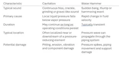
Correctly identifying the hydraulic mechanism should come before selecting the corrective action.
Managing large pressure drops
A conventional restriction orifice is simple, compact and effective in many applications. There are conditions, however, where taking the entire required pressure reduction across a single sharp-edged restriction can allow local pressure to fall low enough for severe cavitation to occur.
An alternative approach is to divide the required pressure reduction among multiple restriction stages.
A multi-stage restriction assembly distributes the total pressure reduction across a series of individual restriction elements. Each stage takes a portion of the differential pressure, with spacing between restrictions allowing the flow and pressure field to develop before the fluid encounters the next stage.
The design is more involved than simply dividing the total pressure drop by the number of plates. Each restriction changes the velocity and pressure conditions entering the next stage. The number of stages and pressure reduction assigned to each depend on flow rate, total differential pressure, upstream and downstream pressures, liquid properties and vapor pressure.
Spacing matters as well. If stages are positioned too closely together, the flow leaving one restriction may not have adequately developed before entering the next.
As the number of stages increases, the physical assembly can become substantially longer. Multi-stage assemblies may include several restriction elements separated by pipe spool sections, with flanged or welded connections between components.
In the opening example involving the 14-inch cooling-water line, a multi-stage restriction assembly evaluated for the service was approximately 40 feet long.
That length introduces additional considerations. The plant must have sufficient installation space. Added pipe and components require support. Existing piping may need modification. Depending on construction, multiple stages can also introduce additional welds and pressure-boundary connections that must be fabricated, inspected, installed and maintained.
This does not make multi-stage restriction assemblies inherently undesirable. Multi-stage pressure reduction is a well-established engineering approach and may be appropriate for many applications.
The important point is that a multi-stage solution is more than several orifice plates placed in series. The hydraulic behavior of the complete assembly, along with its physical length, connections and installation constraints, must be considered.
Other approaches to cavitation control
Multi-stage pressure reduction is one method of addressing severe pressure-drop applications, but it is not the only approach.
Another method is to engineer the restriction itself so that fluid behavior through the pressure-reducing element is more deliberately controlled.
The objective is not simply to size a hole for the required flow and accept whatever cavitation develops downstream. The objective is to influence how the fluid accelerates, where the lowest-pressure region develops, how pressure recovers and where the vapor cavities ultimately collapse.
This is where single stage anti-cavitate technology may be considered.
Rather than distributing the total pressure reduction across a series of separate stages, a specially engineered single-stage flow path can be designed to manage the cavitating flow within the geometry of the restriction itself.
The internal flow path can influence velocity and pressure recovery so that the most aggressive portion of the cavitation event is managed within the engineered flow element rather than allowing uncontrolled vapor collapse to occur farther downstream against the pipe wall.
This is a different engineering approach from conventional multi-stage pressure reduction. One method divides the pressure drop among multiple successive restrictions. The other uses the geometry of a single engineered flow path to influence the development and collapse of the cavitating flow.
The appropriate solution depends on the application, including flow rate, differential pressure, upstream and downstream pressure, liquid vapor pressure, temperature, pipe size, installation space and operating duty.
Recognizing the signature
A piping system that produces a continuous hiss, grinding sound or severe localized vibration during a specific operating condition should not necessarily be diagnosed as water hammer or attributed to a nearby pump.
Look at the pressure-reducing elements. Consider where velocity is increasing and where local static pressure may be falling below the liquid’s vapor pressure. Determine whether the noise continues as long as the operating condition exists or occurs only during a sudden change in flow. Inspect downstream piping for localized erosion or pitting.
A component as simple as a restriction orifice plate can create complex hydraulic behavior when it is asked to absorb a significant amount of energy.
Once the source of the problem is correctly identified, engineers can evaluate the available corrective actions. Depending on the system, that may involve changing operating conditions, modifying the pressure reduction, redesigning the restriction, using a multi-stage restriction assembly or applying an engineered anti-cavitation flow element.
In the case of that violently shaking 14-inch cooling-water line, the piping was not reacting mysteriously to a heat exchanger flowing backward. It was displaying the characteristic signs of a hydraulic condition occurring every time the bypass system was placed into service.
The simple restriction in the line was creating a not-so-simple problem.
Recognizing that distinction is the first step toward solving it.
About the Author
Jeff Chappel
Chief Engineer at Restrict Flow L.L.C.
Jeff Chappel is Chief Engineer at Restrict Flow L.L.C. His experience spans aerospace, nuclear power, systems engineering and industrial flow control. He holds a bachelor’s degree in aeronautical engineering and an Executive MBA. Contact Restrict Flow at (866) 544-7544 or [email protected].