How to use process diagnostic capabilities in pressure transmitters to improve plant performance
The advanced diagnostic technologies available today are like having technicians in the plant all the time checking loops and watching for process problems developing.
Process plants can have dozens or even hundreds of pressure transmitters in a variety of roles (Figure 1). Some instrumentation technicians will describe such transmitters as providing an important process variable. Others may mention how they also send diagnostic information able to warn of an internal problem developing. Increasing numbers of technicians point to today’s advanced transmitters and credit them with being a critical process and automation infrastructure diagnostic tool. Maybe that seems like a lot to attribute to a basic piece of instrumentation, but it is true. Every user may not be taking advantage of the capabilities, but the latest generation of advanced transmitters available now have that high a degree of sophistication.
The range of such diagnostic functionality for a given transmitter depends to a large extent on its design specs and age. Some low-end transmitters deliver a single variable and that’s it. Others may have been top-of-the-line 10 or 15 years ago before today’s capabilities were fully developed. For the most part, the internal electronic diagnostics emerged first. These can send warnings of problems developing with the sensor itself or the signal processing circuits.
Diagnostic information like this can be transmitted as a HART value superimposed on the normal 4-20 milliamp (mA) wired analog current loop, via a digital protocol such as Foundation Fieldbus or PROFIBUS, or even Wireless HART. When introduced, these diagnostics represented a major advance for reliability and maintenance departments, allowing them to deal with developing problems before they caused an inaccurate reading or full failure. But there was more to come.
Eyes and ears to the process
An engineer adds a pressure or differential pressure (DP) transmitter to a process at a strategic point to gather information used to control a specific function. Pressure loops take all sorts of forms and may involve level and flow measurements. As a result, pressure transmitters send their primary process data to the distributed control system (DCS).
This primary reading is the most important task a transmitter performs. Providing data to the DCS depends on a reliable connection to the process so it can get a reading that reflects the true reality and send a signal to the DCS without distortion capable of making the value inaccurate. These requirements are external to the transmitter itself, but it can still evaluate its situation and report when conditions are not correct.
Let’s look at two critical factors separately: electrical loop integrity and an unimpeded process connection.
Electrical loop integrity
In a typical plant environment where a pressure transmitter is communicating with the DCS using a 4-20 mA plus HART wired analog current loop, there can be a long cable — potentially several hundred feet or more — between the transmitter and the DCS I/O connection. A current loop is very robust and can easily cover such a distance if all the elements are intact. Unfortunately, such is not always the case.
A long cable could easily have a dozen termination points from one end to the other as the cable passes through trays and marshalling cabinets. Screw terminals that have worked loose or have become corroded can cause a signal to be lost completely. A short circuit can also cut off data entirely. Tracking such problems down can be tedious, but operators will hopefully recognize the reading is obviously incorrect or gone entirely and will take appropriate action to create a workaround while technicians locate and fix the fault.
More subtle problems where the reading is corrupted but not drastically enough to be immediately recognizable can cause operators to take the wrong action. Here are two examples of how these can happen:
Leakage current — Some situations can create a partial short circuit where a new circuit path is formed but with too high a resistance to disrupt the signal entirely. Current “leaks” from one side to the other due to moisture or corrosion (Figure 2), which might change the signal level a few mA. For example, if the actual signal is 15 mA and the leakage allows another 3 mA, the DCS will believe the reading is 18 mA and show a corresponding value to the operators. This on-scale failure can cause operators to take improper action or cause a control loop governed by that transmitter to respond incorrectly. If the transmitter sends a signal greater than 18 mA, the system will show a fault because the value will exceed 20 mA.
Increased electrical load — Correct functioning of a loop depends on having a known resistance for the wiring. If wires or terminals are corroded or loose, there may still be contact, but those points may add an additional load just as if a resistor had been added to the circuit. This can reduce the voltage available to the transmitter (Figure 3), which can keep it from reaching a full 20 mA signal. Under those conditions, the transmitter might only send a maximum of 16 mA even though the process calls for something higher. This condition is particularly difficult to recognize because the transmitter might behave correctly through much of its range.
Both these conditions can be detected through manual loop checks by a qualified technician, but few facilities have the resources to do these with sufficient regularity. New advanced transmitters have loop integrity diagnostics that can perform these tests automatically, monitoring the available voltage on a continuous basis. If voltage deviates from baseline conditions, operators and maintenance technicians can be notified immediately to avoid potential process upsets or even safety incidents. Thresholds can be programmed in the configurations to correspond to the criticality of a given loop.
Unimpeded process connection
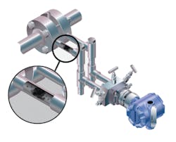
A pressure transmitter can’t do its job if it can’t “see” the actual process condition. As an extreme example, if the transmitter has an isolation valve on the impulse line and the valve is closed, nothing can reach the sensor and it will not reflect the process. Such a situation should be easy to detect, but there can be more subtle conditions where the line is partially plugged or there is some other internal obstruction which causes in inaccurate reading.
Today’s advanced transmitters can perform a plugged impulse line diagnostic (Figure 4) and detect such situations because they listen to the process noise through the connection. If the noise level decreases or changes character and there is no attributable cause, it is likely an obstruction forming in the lines. Once the change crosses a designated threshold, the transmitter can warn operators and maintenance engineers that it may require some attention. If this happens to multiple transmitters at the same time, something has probably gone wrong in the process, releasing particulates into a fluid stream.
Larger process problems
The process noise just mentioned can indicate more than just line clogging. In fact, it can relate to a variety of sources, including:
- Pump and valve cavitation
- Distillation column flooding
- Air entrained in a liquid stream
- Furnace flame instability
- Process leakage
- Agitation loss
Any of these can reduce process efficiency or contribute to equipment wear and breakdown. Discovering when a new problem is developing and locating the source can be a difficult process if the only tools are manual and depend on a skilled technician being in the right place at the right time.
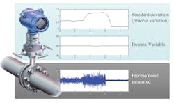
Process intelligence capabilities can be part of pressure transmitters, allowing them to listen to process noise continuously (Figure 5). Once a baseline of normal noise is built into the transmitter’s memory, it can perform statistical analysis to what it hears, listening for patterns deviating from normal and using models to identify a likely source. When a group of pressure transmitters have this capability, they can recognize changes quickly and help zero-in on the source. Operators and maintenance staff can be informed early so the situation can be corrected immediately, if necessary, or monitored until a scheduled shutdown.
Process intelligence can also be used to look for upsets and other conditions capable of creating spikes or dips in normal readings. Such alerts can be logged in individual transmitters and accessed when technicians are doing deep troubleshooting projects. A status log can look back at the last 10 events with time stamps to capture extreme readings for later analysis.
Like adding instrument techs
There probably isn’t a plant in the world that thinks it has too many instrumentation technicians — those people who can go around the plant with their testers and configurators verifying loops, power supplies, wiring and terminations. In many ways, adding pressure transmitters with advanced diagnostics is like adding a group of people to the payroll, fully trained, who know exactly what to look for to make the plant run more reliably and efficiently.
For many plants, it is time to look at those old pressure transmitters and decide how much could be gained by a phased replacement with today’s equipment and the latest best practices.
Megan Wiens is a global pressure product engineer for Emerson’s Automation Solutions business in Shakopee, Minnesota. She is responsible for advanced diagnostic capabilities across the Rosemount pressure portfolio. In this role, she works to implement product solutions that improve plant safety, increase process efficiency and enhance process insight. She holds a bachelor’s degree in chemical engineering from the University of North Dakota.


