Choosing VFD control modes
Modern variable frequency drives (VFDs) share basic similarities with their counterparts from past years. They still need to be configured for the application, with settings applied for voltage, current and other parameters so operation is suitable for the motor and the load. What has changed is the increased variety of operating modes and options now available. In fact, there are so many choices it may not be clear what the guidance is for different applications.
The two main control modes are volts per hertz (V/Hz) and sensorless vector (SV). In general, SV is the more capable mode. However, there are reasons and applications where V/Hz is the right choice. This article describes the pertinent details for each mode, and general cases where each is recommended.
Back to basics
In basic terms, VFDs coordinate two electrical power handling functions through the use of solid-state electronics to control three-phase AC motors (Figure 1). The first step is for the rectifier portion of the VFD to convert AC line voltage to a higher DC bus voltage. The second step is for the inverter portion of the VFD to use the DC bus voltage to generate a varying AC output voltage and frequency to drive the target motor or motors.
Using these means of manipulating electrical power, a VFD can vary the speed of a motor. There are many considerations regarding how serviceable this speed control is for a particular application, such as:
- Minimum controllable speed
- Accuracy of speed control
- Ability to vary torque over the speed range
- Response to varying loads
It is also important to select motors, often labeled as “inverter duty” or “VFD-rated”, specifically designed for use with VFDs. While it is possible to use inexpensive general-purpose AC motors with VFDs, this is usually not recommended for a few reasons.
The first is that a typical fan-cooled motor is designed to cool itself properly at full speed but will cool less at lower speeds. Running such a motor at low speed will not generate enough air flow for the necessary cooling, leading to overheating and subsequent reduced lifespan or motor failure. Inverter duty motors counter this problem with heavy-duty insulation and thermal properties that allow convection cooling to protect against overheating issues. A standard motor may have a NEMA insulation class rating of F, while an inverter duty motor might be rated at H, which increases the allowable operating temperature by 45° F. This adds a substantial margin to the operating range.
Electrically, the rotor in an inverter duty motor is specially designed to maximize efficiency for any control mode, and also improve a VFD’s capability to monitor induced current. As we will see, this latter point is important for SV control.
Classic VFD control: V/Hz
For typical motors, full speed motor operation is achieved at rated line voltage and frequency. For industrial motors in North America, this is quite commonly 480Vac three-phase at 60Hz. Depending on how many poles the motor has, the 100% rated motor speed rotations per minute (RPMs) at full voltage and frequency could be 1,800 (which is very typical), or some other value. The following discussion assumes a motor rated with the preceding values.
A classic V/Hz control scheme would output both the voltage and frequency in a linear fashion, generating 100% motor speed at 480V and 60Hz. Operating the motor at 50% speed would call for 240V and 30Hz. One limitation of this approach is the open-loop nature of this control mode. This occurs because while the VFD is outputting appropriate power values, it really has no feedback about how the motor is actually performing or rotating, so there is no confirmation that the desired speed is being produced. A second limitation is that it may only be able to control a motor down to around 2% or 3% of the speed setpoint, which may not be sufficient for some applications.
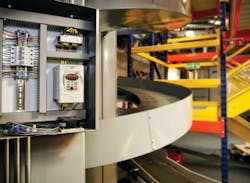
On the beneficial side, many V/Hz VFDs let the user select from other standard or user-defined custom non-linear output curves. For instance, this can tailor the output for high-inertia equipment where a greater starting torque is needed, such as for centrifugal fans and pumps, making them perform better and last longer. Another useful feature of the V/Hz mode is that one VFD can drive multiple motors at the same time, which can be beneficial for equipment like warehouse conveyors where many motors need to operate at the same speed.
While using V/Hz mode doesn’t provide the most accurate speed control, many common pump, fan and conveyor applications don’t require much precision and don’t experience significantly varying loads (Figure 2). If a running load does vary, the motor speed will slow down below the commanded frequency, a condition called “slip.” A VFD operating with V/Hz can’t detect a motor slowdown.
Many VFDs include a tuning mode, where the motor characteristics can be evaluated automatically by the VFD, allowing compensation to be applied. For V/Hz operation, tuning is not required, but it is recommended for best results. In many cases, a new VFD can simply be configured with the horsepower and voltage rating of the target motor and immediately put into service.
Virtually closing the loop with sensorless vector
VFDs operating in SV mode are not really sensorless; they just don’t have an external sensor to obtain feedback from a motor. If an external speed sensor is used, the most common type is an encoder, installed with additional wiring from the motor to the VFD. External sensors may be required for the most accurate control of some types of equipment. However, a VFD operating in SV mode monitors the voltage and current of the motor via the already-connected power leads, and then mathematically determines the motor speed with good accuracy. This is a simpler and less costly solution than installing and connecting an encoder. While not as positive as a dedicated sensor, SV provides sufficient feedback in most applications to enable pseudo closed-loop operation.
Because the VFD now has information regarding the commanded and actual speed, it can vary the output voltage and current to generate the necessary torque, so the motor achieves the desired speed. This form of closed-loop operation is constantly in effect, allowing the motor control system to quickly adapt to any varying load conditions. As compared to the V/Hz mode, the SV mode delivers higher starting torque, tighter speed control under varying loads, the ability for low speed operation down to 1% for maximum rated speed and the possibility of generating up to 200% of rated torque for a brief time.
For a VFD to operate a motor in SV mode, the drive should be tuned for the motor. This is a quick and simple function, usually performed when the equipment is first commissioned. A limitation as compared to the V/Hz mode is that only one motor can be connected to a VFD running in SV mode due to the way the motor windings are monitored.
The SV mode can be used for an application of any type, and it is generally superior to V/Hz mode. Applications with varying loads and speed sensitivity include printing lines, textile manufacturing and CNC machinery operation.
The better or best VFD mode depends on application
Modern VFDs have many operating modes and hundreds of configuration parameters. The most capable units even include on-board logic controllers and PID loops. However, for each application the user must determine the appropriate operating mode.
SV is a more recent development and will provide the best performance for most applications where there is one motor associated with each drive. For good control where the best accuracy isn’t needed, V/Hz is a quick and easy choice.
Kevin Kakascik is a technical marketing engineer at AutomationDirect. Over his 20-year career he has held controls engineering positions for machine OEM’s, entertainment industry systems integrators and material handling systems integrators where he estimated, designed, commissioned and started up systems. Kevin has worked at AutomationDirect since 2013 in technical and marketing roles. He holds a bachelor’s degree in Computer Science and Engineering Technology and an associate’s degree in Electrical Engineering Technology.