5 things to consider when installing variable frequency drives in hazardous locations
The use of electric motors with variable frequency drives (VFDs) has increased substantially in recent decades. The benefits are clear: systems with VFDs operate more efficiently, use less energy, provide more precise control and reduce maintenance costs.
But when a motor is in an environment with combustible materials, gases or liquids, VFD adoption has moved more slowly. To minimize environmental risks, many users have chosen instead to operate their hazardous-duty or explosion-proof motors directly from a power source.
That is changing. Motors that rely on starters must be manually cycled on and off to optimize energy use and control demand. This creates stresses on motors and other mechanical devices, while producing system output peaks. By modulating motor speed automatically, VFDs can accomplish these and other tasks with less dramatic fluctuation, extending motor life and improving system efficiency. Because they control a process at specific speeds, VFDs may also reduce the need for gear trains, belts and gearboxes.
As the industry learns more about the safe application of VFDs on motors in hazardous environments, many are giving them a second look. In these situations, however, not all VFDs are created equal. Before adding one to a new or existing application, it is important to conduct a system review to understand your application’s challenges. Then, select a solution that is safe and complies with applicable regulations.
Some important points to keep in mind include:
1. Confirm that the application’s motor is approved for operation in a hazardous location with a VFD.
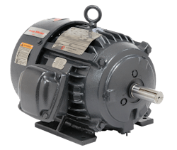
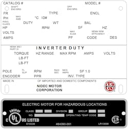
A hazardous-duty or explosion-proof motor can only be used with a VFD if its nameplate clearly says so. That is because VFDs change motor speed by using a pulse width modulated (PWM) waveform that switches voltage on and off thousands of times per second. This rapid cycling creates harmonics that can produce extra heat inside the motor’s windings. You want a motor designed and built to operate at slow speeds without overheating and withstand higher voltage spikes, both essential in combustible situations.
To confirm that your motor is approved for use with a VFD, look for two things when reviewing the nameplate:
- Identification of the motor as inverter duty-rated and confirmation that the inverter rating suits the motor’s application.
- Verification that the inverter duty rating clears the motor for use in the intended hazardous location.
2. Confirm that the motor will be operated within the speed limits listed on the nameplate.
An inverter duty motor for a hazardous environment should be sized based on the minimum speed at which the application can safely run. Inverter duty-rated motors typically include speed range information (found on the motor nameplate) for both constant torque (CT) and variable torque (VT) applications. On a given motor, CT applications, which involve moving solids (e.g., a conveyor), tend to have more limited ranges than VT applications, which include fans, pumps and other applications that move air or water.
A motor’s operating range is described as a ratio that compares its maximum and minimum capacity. For example, a motor with a 10:1 ratio that operates nominally at 1,800 rpm can also run safely at 180 rpm. Because a VFD can impact ratio, the motors they control are tested for agency approval at various speeds and loads to ensure that the combinations’ effects do not invalidate any motor protections.
3. Place the VFD where it delivers the greatest benefit at the least cost.
A VFD can be located either inside or outside the hazardous environment boundaries where your motor is housed. There are advantages and disadvantages to both. Determining the optimal location takes work, including a detailed cost-benefit analysis of options.
For example, a drive mounted near a motor and within the confines of a hazardous location will require an explosion-proof enclosure and other protections. This added expense is spared when the VFD is located away from dangerous conditions. However, any cost savings can be offset by the added cost of the cabling needed to connect the motor and VFD. Depending on the horsepower and the length of the motor cables, motor load reactors or sine wave filters may be required to buffer VFD output — unless the VFD is co-located. Shaft grounding rings may also be needed to protect against premature bearing failures. They are required to be mounted internally to a hazardous-rated motor used in a hazardous environment. Your drive or motor manufacturer may suggest other filtering options to further mitigate risk.
4. Install a VFD system with environmental hazards in mind.
The VFD installation requirements for hazardous-duty or explosion-proof motors are largely the same as those for general-purpose motors. The difference is in the consequences that can result when safe installation procedures are not followed or the motor certification parameters are inappropriate for the area where these inverter duty motors are used.
Proper installation calls for the motor to be grounded back to the drive, and the cabling, conduit and filter must be correctly sized and installed. In addition to the filtering issues cited above, key considerations include:
- Grounding — Stray voltage and static electricity that build up in a system will release themselves through the path of least resistance. Providing a path to the ground minimizes their ability to harm, but grounding an inverter duty motor alone is not enough. The high-frequency current produced by VFDs must be grounded back to the drive. That involves more than running a cable back to the common ground on the drive. The motor should also be grounded back to the drive using a braided grounding wire that is, at minimum, the same size as a single power lead. Power leads and grounding wire should be housed in a metal conduit, connected to both the motor and drive, without isolating either. For optimal mitigation, installers should consider using multiple grounding wires.
- Cable size and length — The farther that cable leads must travel to a motor, the higher the resistance and greater the potential for the motor to overheat due to lower voltages at the motor terminals. The power cables that connect the VFD to the motor must be appropriately sized to reduce this risk. They should also be shielded and rated for use with a VFD. Your manufacturer can recommend cables that are appropriate for your system’s voltage and current limits. When in doubt about total current flow, it is better to err on the side of larger cable and wire sizes.
5. Perform any necessary adjustments once the installation is complete and stay on top of prescribed ongoing maintenance.
Before operating a new VFD system in a hazardous environment for the first time, several parameters in the drive will require adjustment. First, the nameplate data will need to be programmed into the VFD’s motor settings, including the motor’s full load amps and base rpm. The VFD needs this data to trigger excessive load alarms or trips in case of thermal overload.
The VFD must then be programmed with the minimum and maximum speed, while following the guidelines of the safe speed range identified on the motor nameplate. Most VFDs also allow you to set up control strategies for starting, stopping and speed. An additional layer of protection is provided by Safe Torque Off (STO) inputs that provide a safe way to shut down a VFD triggered by an input or protection device. The thermostat connections should also receive special consideration when wiring the motor itself. Often a motor’s inverter duty hazardous rating depends on them for thermal protection of the motor and the environment. While preset by the manufacturer to provide early warning of excessive internal heat, some operators connect the thermostat to their PLC or tie them directly to the E-Stop, STO or Enable control circuits.
During the motor testing period, consider using a lower max speed to help identify system weak points. The acceleration and deceleration settings, which are load- and inertia-dependent, can limit the stresses on and extend the life of mechanical components in hazardous conditions. They also allow a motor to go through multiple start/stop cycles that exceed those offered by across-the-line starters.
As with any VFD system, routine maintenance — including regular removal of any dust buildup on a motor’s exterior — is necessary to ensure long-term, safe operation. Routine infrared camera inspections to look for hot spots can help to forestall problems in hazardous conditions.
The bottom line
While hazardous environments pose challenges to the use of VFD-controlled inverter duty motors, they can be surmounted through careful planning, product selection and installation. The efficiency, productivity and other benefits of these VFD systems will create substantial opportunities for applications in these environments.
Matt Asbill has been an automation specialist at Motion for 27 years. Asbill holds a Bachelor of Science degree in Electronic Technology from Missouri State University in Springfield, Missouri, and a Master of Science in Engineering Technology from Pittsburg State University in Pittsburg, Kansas.
Kyle Mertens is a product manager with 11 years of experience in the electric motor industry. He is currently the product manager for NEMA Horizontal Motors for Nidec’s CIMD-A group. Mertens holds a Bachelor of Science degree in Mechanical Engineering from the Missouri University of Science and Technology and a Master of Business Administration from the University of Missouri–St. Louis.
About the Author
Matt Asbill
Automation specialist at Motion
Matt Asbill has been an automation specialist at Motion for 27 years. Asbill holds a Bachelor of Science degree in Electronic Technology from Missouri State University in Springfield, Missouri, and a Master of Science in Engineering Technology from Pittsburg State University in Pittsburg, Kansas.
Kyle Mertens
Product manager for NEMA Horizontal Motors for Nidec’s CIMD-A group
Kyle Mertens is a product manager with 11 years of experience in the electric motor industry. He is currently the product manager for NEMA Horizontal Motors for Nidec’s CIMD-A group. Mertens holds a Bachelor of Science degree in Mechanical Engineering from the Missouri University of Science and Technology and a Master of Business Administration from the University of Missouri–St. Louis.


