Bulk material handling systems – all you need to know
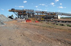
The main function of a bulk material handling system is to continuously transport and supply bulk materials to units in processing plants. Secondary functions include storage and blending.
In a typical bulk material handling system, raw materials (such as bulk solids and powders) are received from trucks, ships or trains. Then they are unloaded to a yard or storage facility, often using a conveyor system. The materials are usually stored in stockpiles.
Material can be reclaimed from the stockpile using an automatic reclaimer or a gravity-reclaim arrangement consisting of reclaim tunnel hoppers and feeders. It is then conveyed to the processing facility. This is true for most bulk material handling systems, whether in processing applications or in moving/storing a final bulk product.
One of the most prevalent equipment types in bulk material handling is a belt conveyor. Although many other types of conveyors are available – such as screw, chain and pneumatic – the most commonly used is the belt.
Belt conveyors are the backbone of bulk material handling systems in many different processing plants. Other equipment used in material handling systems includes stacker/reclaimer machines, hoppers, chutes, feeders and magnetic separators.
The belt conveyor’s role in bulk material handling systems
Designed for continuous operation, a belt conveyor can be used in a wide range of capacities and distances, and its length can be a few meters or tens of kilometers. At either end of the conveyor, the belt wraps around a pulley. This is the most common belt conveyor design. One pulley (usually the one at the head of the conveyor) is coupled to a drive unit to move the belt and transport the materials. Other designs, such as conveyors with three or more pulleys, or those with two or more drive pulleys, are available. However, they are typically used in special applications.
A key component of belt conveyors is the belt, which has a double function: to contain conveyed materials; and to transmit the force (in the form of tension) to move the load. The belt is also one of the most expensive components in a belt conveyor. Many factors – such as materials to be handled, corrosion, impact, tension, strength and elongation – should be considered in careful selection.
Belt conveyor maintenance for bulk material handling
To maintain reliability, the principal belt conveyor components – such as idlers, rollers, pulleys, bearings, shafts and belts – must operate under dynamic loads and harsh conditions. Therefore, if poorly designed or manufactured, they can fail frequently. Rolling element bearings are widely used in different equipment and sometimes offer a short life, even as short as a few months if operating under dynamic or unexpected loads not appropriate for their design. Shafts are similar.
Belts can also be damaged and destroyed under loads that are inappropriate for their design, when experiencing corrosion or in applications unsuitable for their material. Many other factors must be considered in the design, operation and reliability of conveyor belts. For instance, dust and emissions are often present in processing environments. If superior seals are not used for bearings and other components, this equipment can be affected and damaged. On the other hand, if all these components are correctly designed and selected, they can experience trouble-free operation for many years.
In a typical bulk material handling system, raw materials (such as bulk solids and powders) are received from trucks, ships or trains. Then they are unloaded to a yard or storage facility, often using a conveyor system.
Appropriate accessories should be used to clean the belt at the feed and discharge points to increase the life of many components such as idlers and rollers. Belt cleaners and play important roles in a belt conveyor’s reliability, safety and overall environmental conditions of the conveyor and surrounding facilities.
Belt conveyor design for bulk material handling
Many designs are possible for a conveyor’s drive unit. In conventional designs, the power is supplied by a direct-coupled motor gearbox, or by a direct- or parallel-shaft drive, operating the drum through a suitably sized couple. Startup capability, particularly the requirement for startup under full load (when the conveyor is fully loaded with materials), is a major factor that should be carefully considered in the design and sizing of drive units. Many small and medium-sized conveyors use a fluid coupling to ease startup and transient operations. Large and very large conveyors often use variable speed drives.
Another design recently used for some conveyors is the motorized drum. In this arrangement, the electric motor, gear unit and bearings form a complete drive unit inside the pulley’s drum shell, which offers protection. This unit directly powers the belt, eliminating the complication of an external drive and coupling that are used in conventional arrangements. They are particularly popular in revamped and renovated units.
Generally conveyors should be compact and lightweight, making the motorized drum design a good choice, but conveyors have some advantages and disadvantages. They offer compact and better-protected drive units for some applications. On the other hand, access and maintenance may be difficult, and some size and design restrictions exist.
As rough indications, motorized drums have been produced in diameters up to 900 millimeters with power up to 150 kilowatts. Overall, motorized drum units are special designs that should be used in applications in which conventional drive designs will be ineffective or troublesome. Otherwise, conventional designs should be used.
Another design recently used for some conveyors is the motorized drum. In this arrangement, the electric motor, gear unit and bearings form a complete drive unit inside the pulley’s drum shell, which offers protection.
The drum diameter is dimensioned according to the class and type of belt and to the designed pressures on its surface. The shell face of pulleys might be clad in rubber with a thickness determined by the operational details and the power to be transmitted. Patterns for rubber cladding may be grooved in a herringbone design, horizontally grooved based on the direction of travel or diamond grooved. These are designed to increase the coefficient of friction.
A tension or take-up unit is an important but often overlooked component for any belt conveyor. This unit should provide and maintain the force (belt tension) necessary to ensure that the belt continuously contacts the drive pulley. In small and non-critical conveyors, a simple screw type unit is specified and used. This is the simplest and least expensive tension-unit type, and it always needs operator attention for adjustment and control. A counterweight tension unit (often known as a gravity take-up unit) is the most widely used in many belt conveyors. In these units, the belt tension is provided by a properly calculated weight (usually installed in a special unit near the drive pulley at the head of the conveyor), which can be adjusted easily. This system is reliable and robust and provides high performance.
For large conveyors or special applications in which compact, lightweight options are needed (for instance, conveyors on mobile or moving units such as stacker/reclaimer machines or unloader units), a motorized winch take-up or hydraulic take-up unit is used. A counterweight unit or take-up unit should provide constant tensional force to the belt regardless of the operating conditions and transient cases. Its force (provided tension in the belt) is designed according to the minimum tension limits necessary to guarantee the belt pull and to avoid unnecessary belt stretch. The designed movement of the take-up unit is derived from the elasticity of the belt during its phases of operation with limits. As very rough estimates, the minimum movement of a tension unit should not be less than 2 percent of the distance between the centers of a conveyor using plastic/textile-woven belts or 0.5 percent of a conveyor using steel-corded belts.
The role of belt trippers in bulk material handling
Belt trippers are specifically designed to discharge the material from the belt at one or more points or along the length of the conveyor. They are an important element of many bulk material handling systems, but often receive little attention. They are typically designed for continuous operation. However, poor designs and manufacturing of some trippers have resulted in poor operation and unsatisfactory reliability.
Trippers can create multiple discharge points for a belt conveyor. Typically, belt conveyors only discharge a bulk material from the end of the belt. Belt trippers are specially designed equipment, most often in the form of short belt conveyors that can be positioned along a main belt conveyor to trip or divert the flow of the bulk material through a chute or similar apparatus for controlled discharge.
Belt trippers can be stationary or mobile. Less common are stationary trippers that discharge materials at the same location. However, movable belt trippers are widely used. For example, they are used to load large stockpiles or bunkers or to spread material over a large area. Even a special tripper is designed to load individual bins or bunkers by moving across the top of them.
Belt trippers are specifically designed to discharge the material from the belt at one or more points or along the length of the conveyor. They are an important element of many bulk material handling systems, but often receive little attention.
Movable trippers have a frame mounted on flanged wheels, which engages rails parallel to the belt conveyor. They are designed with a one- or two-sided chute, so the conveyor can discharge material on either side. Tripper cars are usually powered by an electric drive, although many other different drive systems have been used. Properly designed trippers can build and maintain large-volume stockpiles by discharging material on either side of the conveyor and creating custom heights, lengths and locations of stockpiles.
An overhead belt conveyor tripper is mounted on the top of a silo or bunker, which improves the structure of a traditional belt conveyor tripper and requires less switch time. This is true when compared to a traditional shuttle belt conveyor tripper. It provides quieter operation and precise location. For modular design, the equipment was downsized in volume and weight by around 50 percent.
Stacker/reclaimer machines in bulk material handling
Stacker/reclaimer machines are used to stack and store materials in stockpiles and stockyards and to reclaim materials when needed. Old-fashioned separate stacker and reclaimer machines have been used for decades, but modern designs favor combined stacker/reclaimer machines. They are efficient options that offer great operational flexibility.
During stacking mode, material is fed on a boom conveyor and then distributed in stockyards. In reclaim mode, the boom conveyor discharges materials on the stockpile conveyor for feeding to bunkers, silos or consumers through other conveyors and transfer points. Some conveyors in this system can be reversible depending on the layout requirement. Stacker/reclaimer machines using bucket wheels or moving on rail tracks are commonly used in material handling systems.
A bucket wheel mechanism is usually driven by a variable frequency electric motor. The reclaiming capacity can be adjusted by changing the rotational speed of the bucket wheel. The drive system is equipped with over-force protection units. When the digging force of the bucket wheel is higher than the set value (which is determined for each application based on comprehensive practical tests and an operational study), an alarm sounds, and the reclaiming capacity is reduced to decrease the digging resistance to protect the bucket wheel system.
The bucket mouth experiences severe wear and damaging forces. It is made of wear-resistance materials, such as tungsten carbide, featuring high-level wear resistance and structural rigidity. The bucket tooth and the bucket shell are connected by specially designed bolts to ensure convenient replacement. Bucket teeth are made of ferromagnetic materials with high-level wear resistance and drop-proof capabilities.
The boom conveyor must operate under different inclination angles. All its components – such as the driver, brake and backstop system – should be designed with special consideration to this requirement. Often the most difficult case for the driver sizing and other system components is the maximum inclination angle with full loads.
Another difference between conveyors of stacker/reclaimer machines and other conveyors in the plant is the take-up device. For many conveyors, gravity take-up is commonly specified and used. However, automatic hydraulic belt take-up devices are used in conveyors for stacker/reclaimer machines. These hydraulic systems are highly flexible and capable of automatically detecting deviations and correcting them.
Stacker/reclaimer machines are used to stack and store materials in stockpiles and stockyards and to reclaim materials when needed. Old-fashioned separate stacker and reclaimer machines have been used for decades, but modern designs favor combined stacker/reclaimer machines.
The speed of movement is an important parameter for stacker/reclaimer machines. Speeds of the machine in operation mode and relocation mode should be variable in a suitable range to allow for proper operation. Generally, their operational speed is in the range of 5 to 12 meters per minute (m/min), and for large and big machines, the lower range should be selected. The relocation speed is often in the range of 15 to 30 m/min. High relocating speed would cause the boom to swing or cause instability, which can potentially result in damage, fatigue or breakdown of the steel structure following long operation times. Lower speed is often encouraged to reduce the startup and braking time and impact effects. On the other hand, operational requirements should be met and an optimum speed range should be selected.
Many discussions and disagreements arise regarding the maximum relocation speed of stacker/reclaimer machines because higher speeds often require a more stable machine, stronger structures and more power. These requirements are expensive. A good recommendation is always to differentiate clearly between what the machine’s capabilities are and the range recommended by the manufacturer. Both should be noted with all details. Also, proper calculations, studies, simulations and technical details for specified maximum speed and all associated conditions should be provided.
After clearly defining what the machine can do, the end user should understand if the manufacturer wants to recommend a preferred relocation speed range for a machine. In operation, relocating at very low speeds, even lower than the conservatively recommended values, is suggested unless an urgent operational requirement mandates fast relocation at the maximum recommended speed.
Hoppers & chutes in bulk material handling
Hoppers and chutes are used for feeding bulk materials to other equipment, mainly belt conveyors. The main function of hoppers is to store the materials next to equipment for feeding.
Chutes are usually only used to guide and feed materials to the next equipment and not for storage, although in practice, they should be able to store some volume of materials in case of emergency, for instance, if a piece of equipment upstream of the system malfunctions or surges.
They usually feed materials with constant discharge. Stoppage of material, such as arching or ratholing does occur sometimes.
Arching occurs when an obstruction in the shape of an arch or a bridge forms over the chute, silo, bunker or hopper outlet because of the material’s cohesive strength. When a stable arch forms above the outlet, discharge is prevented, and no material can flow.
Hoppers and chutes are used for feeding bulk materials to other equipment, mainly belt conveyors. The main function of hoppers is to store the materials next to equipment for feeding.
Ratholing occurs when material flows in a channel located above the chute, silo, bunker or hopper outlet. As the level of material in the flow channel drops, resistance to further flow into this channel occurs because of the material’s cohesive strength. If material has enough cohesive strength, the stagnant material outside the flow channel will not move into it, forming a stable rathole. Once the flow channel has emptied, no further material discharge will occur from the outlet resulting in a no-flow condition. In addition to causing a no-flow condition, ratholes significantly reduce the live capacity of a bunker, silo or stockpile. Combinations of these two may also occur – such as when flow obstructions switch or interchange between arches and ratholes and erratic flow results.
These problems can be rectified with many solutions such as vibration-induced forces. When an arch or rathole form, it can be removed by vibrations transmitted to the hopper or silo, and then material flow will resume.
However, a passive solution is well-designed chutes, hoppers and bunkers. One example is including a minimum valley angle, around 65 to 75 degrees, in the vessels. The angle depends on the materials and operational details to help avoid such stoppage and other issues.
Amin Almasi is a senior rotating machinery consultant in Australia. He is a chartered professional engineer of Engineers Australia and IMechE and holds bachelor’s and master’s degrees in mechanical engineering and RPEQ. He is an active member of Engineers Australia, IMechE, ASME and SPE and has authored more than 100 papers and articles dealing with rotating equipment, condition monitoring, offshore, subsea and reliability. He may be reached at [email protected].