Basic concepts in pneumatic conveying

Pneumatic conveying pertains to the transport of solid particulates with moving carrier gas (typically air). The drag force generated by the slippage between the gas and the particles (or ensemble of particles, such as a packed bed) overcomes the frictional losses and gravitational force, providing the necessary energy to move the particles from a source to a destination. Once the gas velocity exceeds a particle's terminal velocity, that particle becomes entrained in the gas flow, although, for bulk solids, that velocity tends to be a little higher than the terminal velocity as particles can cluster together.
Depending on the gas velocity and the material characteristics, a wide range of flow-patterns can be observed, as shown in Figure 1. At a constant solids feed rate, as the gas velocity increases, the packed bed will transform into a moving slug flow, which will then degenerate into dunes or unstable dunes, and then eventually the particles will fully entrain into the gas stream resulting in homogeneous flow. With homogeneous flow, particles move much faster, but the solids concentration is much lower. Increasing the solids concentration at a constant gas velocity has the opposite effect. The hydrodynamics go from homogeneous flow to dune flow, then slug flow, and eventually plug as a packed bed.
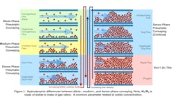
This range of hydrodynamics offers a wide range of applications. Homogeneous flow is relatively easy to manage, while dune flow and slug flow are trickier but may be necessary for some applications. Lower gas velocity, higher solids concentration conveying is called dense phase, while higher gas velocity, lower solids concentration conveying is called dilute phase. Medium dense phase or strand phase (sometimes called mixed phase) conveying is between these two regimes and requires careful control of gas velocity at the material pickup point to avoid unstable flow conditions.
To understand the differences between dilute and dense phase conveying, it is best to look at the solids flow rate (carrying capacity) or the pressure gradient versus the gas flow rate in a horizontal pipe, as shown in Figure 2. If we look at the carrying capacity with respect to the gas flow rate, we see that the carrying capacity at a given system pressure drop reaches a maximum as the gas flow rate increases. The higher the pressure drop across the system, the higher this maximum. In general, this maximum is the transition point between dense and dilute phase conveying. You might think this would be an ideal operating condition, but it is not. The flow hydrodynamics at the maximum carrying capacity corresponds to the saltation flow, which is the point at which, if the gas velocity decreases, particles will drop (or salt) out of the flow stream. At this point flow is unstable, and operating at or near this point in a commercial system is challenging. Dilute phase systems are design to operate at gas velocities slightly above the saltation velocity. Dense phase systems operate below this point.
The pressure gradient versus the gas flow rate curve (in Figure 2) for single phase gas flow (zero solids rate) approximately follows a monotonic, velocity squared trend. However, once solids are added to the horizontal conveying line, a dramatic change in the pressure gradient occurs. This is because the added solids result in additional pressure drop contributors such as particle acceleration, particle shear stresses, and particle-wall friction, all of which are much more significant than the corresponding gas acceleration, gas shear stress, and gas-wall friction.
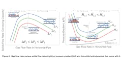
As Figure 2 shows, for the pressure gradient versus gas flow rate plot, it is best to operate near but not on or too close to the saltation flow line. This is where the pressure gradient is the lowest, which means less capital and lower power consumption. In addition, for dense phase flow, which is left of the saltation flow line, gas flow that is too low can result in a packed bed that plugs the line and does not move. The pressure gradient and pressure fluctuations in dense phase mode are higher than in dilute phase mode and manifest as vibration in the conveying line. For dilute phase flow, which occurs at high gas velocities and to the right of the saltation flow line, the pressure fluctuates less, creating fewer concerns about mechanical stress from vibration.
Dilute versus dense phase conveying
Dilute phase conveying occurs when the gas flow rate (gas velocity) is sufficiently high to fully entrain the transported solids. Typically for dilute phase conveying, the superficial gas velocities tend to be over 4,000 ft/min, with solids loading less than 15 mass of solids to the mass of gas (i.e., 15 lbm of solids/lbm of gas). The particles tend to be fully suspended. There is no stationary layer, moving dunes, strands, or plugs at the bottom of a horizontal conveying line section, or recirculation patterns in a vertical section. As previously noted, slightly above the saltation velocity should be considered the absolute minimum gas velocity to operate a dilute phase conveying line.
Several references in the literature define dilute phase conveying by the conveying pressure drop (less than 1 bar) or solids loading ratio (mass of solids/mass of gas) less than 15. As noted, such operating characteristics are typical, but dilute phase conveying is not bounded by these operating limits. For instance, a long-distance dilute phase conveying system can operate at a pressure drop of more than 3 bars.
Dense phase conveying occurs at much higher solids concentrations but lower gas velocities — around 200 to 600 ft/min at the pickup point, with end-of-line velocities not exceeding 1,600 to 2,000 ft/min. This tends to be below the saltation velocity, and as expected, particles are not in suspension. Various flow patterns may develop depending on the nature of the particles (fine versus coarse) and the conveying line orientation. As shown in Figure 1, for horizontal lines and fine powders, the solids flow just below the saltation velocity is dune flow. As the gas flow decreases further, dune flow transitions into slug flow. Many materials can be conveyed in stable slug flow (such as plastic pellets), but such systems require additional design features to achieve stable and reliable conveying. The airflow control in the line must be “smart” to prevent the flow regime from becoming unstable, and shock-absorbing line supports must added to prevent line failures due to high dynamic loads. The operating window for a stable dense phase conveying is narrow, and the control system must modulate constantly to keep the operating point within the stable zone.
Since conveying velocity strongly affects particle breakage (attrition) and abrasive wear of the conveying line and system components, dense phase conveying mode is desirable where erosion or attrition is problematic. The lower gas flow rates also reduce the size of the filters and gas conditioning system, especially in systems that need to use gas other than air. However, dense phase conveying is not always possible, feasible, reliable, or economical. Consider the following factors when selecting the most suitable conveying mode.
Material Factors. Dense phase conveying may not be suitable if:
- The particles are fibrous, sticky, moist, wet or cohesive.
- The particles are very dense.
- The particles are very soft, pliable and elastic/rubbery.
- The particle size distribution is very broad, with 10-25 wt% fines fraction smaller than 425 mesh.
- The particles have no natural slugging ability (e.g. Geldart B, high permeability). Such materials may require special gas injection systems or bypass systems along the conveying line, which requires access to the line for maintenance.
- The maximum particle size is smaller than 50 millimeters.
- The incoming feed material properties are highly variable.
Operational Factors. Dense phase conveying may not be suitable if:
- A significant turn-down (Max/Min > 5) in conveying rate is desired.
- A high-pressure conveying gas source is not available.
- Vacuum conveying is required to convey solids from multiple sources to a single destination. Vacuum-based dense phase conveying systems have a limited feasible conveying distance.
- The conveying and drying steps are combined. The total gas flow rate may not be sufficient for drying.
Configurational Factors. Dense phase conveying may not be suitable if:
- The required capacity is very high, or the conveying distance is very long.
- Conveying line supports cannot be properly supported along the conveying length due to structural considerations. This is a common problem for retrofit situations.
- Cross-contamination is an issue.
- The system size is tool large or the pressure limit too high for available components.
While dilute phase conveying systems are more common, reliable, inexpensive and simple to design and operate, dense phase conveying systems offer the significant benefits of lower product degradation and system wear. For instance, dense phase conveying of polymer pellets dramatically reduces fines and streamers/floss generation. Table 1 provides a list of the pros and cons of dilute versus dense phase conveying.
Designing a conveying system
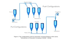
Conveying lines can be designed in a push (pressure) or pull (vacuum) configuration, as shown in Figure 3. Dense phase conveying systems primarily use the push configuration, but dilute phase systems can use either configuration depending on the processing requirements. A push configuration is where the gas mover is located before the conveying line and is recommended for conveying from a single source to multiple destinations. A pull configuration is where the gas mover is located after the conveying line and may be the correct choice for conveying from multiple sources to a single destination. Note that conveying lines in the pull configuration operate under a vacuum, so all components must be compatible with that vacuum, especially the hoppers.
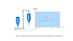
As with most flowing operations, friction dominates the pressure drop and is the key design parameter. The pressure drops across all horizontal, riser, and bend sections must be determined. Figure 4 illustrates what the absolute pressure and superficial gas velocity could look like in a typical conveying line. The pressure will decrease as the material moves down the line (from source to destination), resulting in an increasing velocity — something to consider if erosion or particle attrition could be an issue at higher velocities.
Figure 4 also shows subtle pressure changes followed by significant pressure changes or regions of high pressure drop. These result from bends in the conveying line. Bends are almost always the most significant contributors to pressure drop because the wall friction is higher and the particles need to reaccelerate, especially with dilute phase conveying. As a result, for a smooth-running system with the lowest capital and operating costs, design the conveying lines with the lowest number of bends possible.
For a given system configuration, the target conveying rate and conveying velocity of pickup (greater than the saltation velocity) determine the system pressure drop (ΔPsystem). Adjust the air mover characteristics to match the pressure-flow rate combination or iterate the flow rate until the pressure drop in the line matches the delivery pressure of the air mover and the gas delivery from the blower matches the conveying gas flow rate.
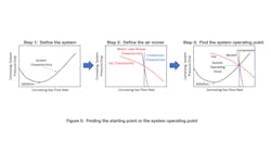
The preliminary design of a pneumatic conveying system involves three steps, as shown in Figure 5. First, the system must be defined, which includes accounting for all the factors contributing to pressure drop. However, not all contributors are equally significant for dilute or dense phase conveying. For dense phase conveying, gas velocities are low, which means solids velocities are lower and particle acceleration is not significant. There are several factors to consider, but fortunately, tools are available that make this assessment easy. Most of the work is based on the following principle:
ΔPsystem =
ΔPair-supply + ΔPacceleration + Σ ΔPhorizontal-sections + Σ ΔPvertical-sections + Σ ΔPbends + ΔPgas-solid-separator
ΔPair-supply = ΔPsilencers + ΔPfilters + ΔPheat-exchangers + ΔPair-piping
With the overall pressure drop versus the range of possible gas flow rates for the system determined, the next step is to choose and size the air mover. The types of air movers or gas movers commonly used for pneumatic conveying are:
- Fans and centrifugal blowers;
- Rotary lobe positive displacement blowers; and
- Compressors (screw, centrifugal, reciprocating).
These air movers are based on very different operating principles. It is a good idea to become familiar with their characteristic curves, which relate to the gas volumetric flow rate, inlet and outlet pressures, speed, temperatures, system configuration and brake horsepower, which can all be obtained from the vendors. As Step 2 of Figure 5 shows, the choice of air mover is dependent on the absolute pressure and range of gas flow rates. Most conveying lines use fans and centrifugal blowers because, even though they cannot handle significant changes in pressure drop, they can handle a wider range of gas flow rates.
Once the air mover has been chosen, the next step is to overlay the system characteristic line with the air mover characteristic line, the intersection of which is the system operating point. This is your starting point for the preliminary design. However, there are some additional guidelines to consider. When designing a new conveying line (or assessing an existing one):
- Have a clear understanding of desired transfer rates (average, instantaneous, catch up).
- Follow best practices for line configuration. Do not route conveying lines like utility lines in the plant.
- Consider special requirements for gas conditioning (temperature, humidity, inert).
- Remember that pressure decreases with the flow down the line, which means that the gas velocity increases (i.e., material balance needs to be conserved).
- Evaluate any prior experience conveying similar materials. Extract data from currently operating systems. Identify and address failure modes.
- For new materials, determine whether to convey in dense or dilute phase. Is the material sensitive to attrition? Is the material erosive? If so, consider dense phase conveying.
- Testing will be required using representative samples. Can testing be done at conditions similar to plant operating conditions? What is the value and reliability of the data?
- Set maintenance requirements and reliability goals.
Common design errors
As with all types of engineering projects, pneumatic conveying systems have common design errors that can lead to pitfalls during operation.
Dilute phase systems. Common design errors encountered when troubleshooting dilute phase systems include:
- Providing insufficient straight length for material acceleration between the feed point and the first elbow. This can cause premature line plugging, especially at higher loadings or when operating close to optimal saltation velocity.
- Using too many bends or flexible hose will increase pressure drop or reduce conveying capacity.
- Using upward inclined conveying lines to shorten conveying distance.
- Using back-to-back bends will cause the material to slow in the second elbow and possibly plug the line.
- Failing to accurately account for the air leakage from a rotary airlock/feeder. Leakage will increase with wear over time as well.
- Improper feeder venting for positive pressure systems.
- Pickup designs that create low-velocity regions, allowing material accumulation and unstable entrainment.
- Failing to account for temperature increase across the blower due to heat of compression. This can result in excessively hot conveying air, which can degrade or soften the material and potentially lead to plugging.
- Failing to account for line losses for air piping, heat exchangers, silencers and filters in the overall delivery pressure, which will result in an undersized air mover.
- Using an air mover operating pressure that is too close to the relief valve setting, which can cause intermittent loss of conveying air.
- Lack of instrumentation (pressure, temperature and flow measurement), which makes it difficult to troubleshoot, catch a potential issue or optimize a system after startup.
- Using an undersized blower at high rpm and near its motor’s upper horsepower limit, which leaves little room for error in pressure drop or expected differences in material characteristics.
Dense phase systems. Common design errors in dense phase systems include:
- Failing to critically question the material’s suitability for dense phase conveying. Conventional dense phase conveying does not work with all materials. Often, reliable dense phase conveying requires special techniques, such as air injection or bypass systems, the selection of which should be technology-driven and not vendor driven.
- Failing to conduct conveying trials for materials with no prior dense phase conveying experience to establish feasibility and reliability. For existing materials, generate high-quality data by instrumenting operating systems in the plant. When testing materials:
o Be sure the sample is representative.
o Try to replicate process conditions to the best of your ability. Be prepared to account for deviations during normal operation.
o Account for product variability.
o Test at a reasonable scale (line diameter and length) for reliable scaleup.
- Inadequate use of line supports and shock absorbers (for larger systems). Line vibrations are an inherent characteristic of dense phase conveying, especially when operating in slug flow. Vendors must provide reliable calculations for dynamic loads, and civil engineering must account for the stresses in the design.
- Inadequate airflow control and management, which can cause unstable operation and result in excessive line vibration and system failures.
- Failing to account for high volumetric gas flow rates required to purge the line between products, which can cause cross-contamination problems. Process filters must be designed for such high purge flow rates.
- Inconsistent feed rate operations. Dense phase systems have limited turn-down ratios compared to dilute phase systems and work best with consistent feed rates.
- Inadequate line connectors. Connectors must be robust to withstand conveying pressures and line stresses to avoid failures.
Final note
Pneumatic conveying systems can transport materials with lower costs, less contamination, reduced maintenance, greater flexibility of routing, less dust exposure and a smaller footprint than mechanical conveyors. However, proper system design, along with an effective training program and a regular maintenance schedule, are critical to ensure years of efficient and reliable service.
Ray Cocco is president and CEO of Particulate Solid Research, Inc. (PSRI), an international consortium of companies focused on the advancement of technology in the multiphase flows with granular and granular-fluid systems.
Shrikant Dhodapkar, PhD, is a senior fellow in the Dow Plastics Process R&D Organization at Dow, Inc.
PSRI
Dow Inc.
About the Author
Ray Cocco
President and CEO of Particulate Solid Research, Inc.
Ray Cocco is president and CEO of Particulate Solid Research, Inc. (PSRI), which is an international consortium of companies focused on the advancement of technology in the multiphase flows with granular and granular-fluid systems. He has over 30 years of experience in reactor engineering, modeling, fluidization, and particle technology. He has worked on ceramic processing, oxydehydrogenation, catalytic oxidation, hydrogenation, hydrodesulfurization, composite materials, biomass, chemical looping, polyolefin, chlorination, and oxychlorination. Ray was the past chair of the AIChE Particle Technology Forum (Group 3), a past member of the AIChE Chemical Technology Operating Council (CTOC) and is currently an AIChE fellow. He has over 80 publications, three book chapters, several patents, and numerous invited presentations and regularly consults for industry, national labs, and universities. He holds a B.S. in chemical engineering from the University of Florida and a Ph.D. in chemical engineering from Auburn University.
Shrikant Dhodapkar
Fellow, Packaging & Specialty Plastics Process R&D, Dow, Inc.
Shrikant V. Dhodapkar is a senior fellow in the Dow Plastics Process R&D Organization at Dow Inc., (Lake Jackson, TX, 77566; phone: 979-238-7940; email: [email protected]) and a fellow of the American Institute of Chemical Engineers. Shrikant holds a Bachelor of Technology (B.Tech.) degree in chemical engineering from the Indian Institute of Technology, New Delhi (India) and earned M.S. and Ph.D. degrees in chemical engineering from the University of Pittsburgh. During the past 30 years, he has published extensively on various aspects of solids processing and contributed chapters to several handbooks, including the ninth edition of Perry’s Chemical Engineering Handbook. He has extensive industrial experience in designing and troubleshooting solids processing plants, with special expertise in pneumatic conveying, silo storage, separation, fluidization, drying, particle and powder characterization, mixing/blending, dosing, and coating technology. He is the past chair of AIChE’s Particle Technology Forum and past member of Chemical Technology Operating Council.