Selecting a feeding device for a pneumatic conveying system

Bulk solid materials can be fed into a pneumatic conveying system using several mechanisms. The two main factors that determine the most suitable feeding device are the material’s flow properties and the feeding device application.
Material flow properties
For this article, we will classify all materials as free flowing, fluidizable or compactable and cross reference those terms to the Geldart classification model, which is a useful tool for understanding a material’s flow properties. The Geldart model classifies materials into four groups based on particle diameter and the density difference between the particles and the fluidizing gas.
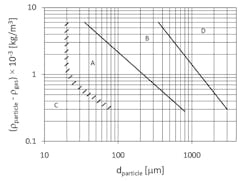
Free flowing. A free-flowing material contains at least 90% particles larger than 60 mesh (250 microns) and 100% particles larger than 200 mesh (75 microns). The material flows from a storage vessel at a controlled rate, depending on the size of the vessel discharge opening. The material exhibits an hourglass flow characteristic, which is both predictable and dependable. These flow characteristics are typical of Geldart Group B or D materials.
Fluidizable. A fluidizable material is usually finely ground, with most particles smaller than 100 mesh (150 microns). The material packs solidly when deaerated and, when piled on a flat surface, will stand up vertically when some material is scooped away from the pile's base. Yet when mixed with a small amount of air, the material entrains air between the particles, eliminating interparticle friction and causing the material to flow like a liquid; hence the term fluidizable. In storage bins and hoppers, the material frequently bridges across the discharge outlet or compacts in some areas. Then, when the material breaks loose and falls, it can fluidize and flow uncontrollably out of the container. These flow characteristics are typical of Geldart Group A and some Group C materials.
As the material fluidizes, its bulk density decreases to a lower value, referred to as the fluidized density. When applying equipment that is sized on a volumetric basis, such as rotary feeders and airlocks, screw feeders and conveyors, or weigh hoppers that must hold a specific mass weight of material, it is important to use the material’s lower, fluidized density. Using the higher bulk density can result in the equipment being undersized and unable to achieve the desired mass flow rate.
Compactible. A compactable material is cohesive. The material can consist entirely of very fine particles (100% less than 325 mesh [50 microns]) or primarily of very fine particles with some coarse particles. When the compactable material consists of 100% very fine particles, it cannot be fluidized because the very fine particles have an interparticle attraction that causes them to stick together. Attempting to fluidize the compacted material with air can form cracks or breaks in the compacted material bed that allow the fluidizing air to escape while doing little to enhance flow. Sometimes, a form of mechanical intervention into the material is necessary to cause the initial fracturing to occur, allowing the air to escape but still not creating any beneficial fluidization. These flow characteristics are typical of Geldart Group C materials.
When the compactable material consists of very fine particles mixed with some coarse particles, applying a normal amount of fluidizing air tends to segregate the fine and coarse particles. Applying excessive fluidizing air can fluidize the coarse particles, but the fines act as a mortar to hold the coarse particles together, preventing either free flow or fluidized flow from the storage container.
Feeding device applications
A feeding device can be used in four major pneumatic conveying applications: controlling discharge from a storage container, controlling feed into a vacuum conveying system, controlling discharge from a vacuum receiver, and controlling feed into a pressure conveying system. Depending on the application, the feeding device may be referred to as a feeder, an airlock or a combination feeder-airlock.
Controlling discharge from a storage container. When storing the material to be conveyed in a silo, day bin, holding tank or feed hopper, its discharge must be controlled. In such an application, little or no pressure differential exists between the container and the conveying system — typically only a few inches of water column resulting from the conveying system being connected to dust collection equipment.
Because the material discharges from the container by gravity into a process, another container or a mechanical conveying device, the feeding device will only control the material discharge rate. The term “feeder” is suitable for this application.
Controlling feed into a vacuum conveying system. Similar to the previous application, this application controls material discharge from a silo, day bin, holding tank or feed hopper. But in this case, air flows into the conveying system in the same direction as the material feed. Although a slight pressure differential exists, it is in the direction of the material feed and can affect the material flow by inducing fluidization or flooding.
We can also use the term “feeder” for this application because the material discharges by gravity into a vacuum conveying system and the feeding device only controls the material discharge rate.
Controlling discharge from a vacuum receiver. Typically, a feeding device is used on a vacuum receiver's discharge to prevent air leakage into the vacuum receiver, not to control the material discharge rate. The vacuum conveying system delivers the material to the vacuum receiver at a controlled rate, so the feeding device at the bottom of the receiver only needs to discharge material at that rate and does not need to provide further flow rate control.
However, because the vacuum receiver may be under vacuum up to 18 inches mercury, a large amount of airflow could be drawn into the receiver. Because material must discharge from the receiver at the same time air wants to flow in, the material and air are trying to pass in opposite directions, which can impair material flow. In this application, the feeding device is correctly called an “airlock” rather than a feeder. The device works like a revolving door at a building entrance, permitting material to discharge but restricting airflow from entering the receiver.
Controlling feed into a pressure conveying system. This application is the most difficult of the four because it simultaneously controls material feed into the pressure conveying system and prevents air from escaping the conveying line. The difficulty varies depending on the material characteristics and the head (or depth) of material on top of the feeding device. The feeding device is correctly called a “combination feeder-airlock” in this application. Selecting the wrong device for this application has caused many conveying system problems, and choosing the right device requires a comprehensive understanding of the application.
Types of feeding devices
The most common feeding devices include orifice, screw conveyor, vacuum nozzle, venturi, rotary valve, lock hopper, screw pump and pressure vessel. Each device can be classified as a feeder, an airlock or a combination feeder-airlock, depending on how the device functions and the material it is handling.
Orifice. An orifice controls material flow by controlling the size of the storage container discharge opening. The orifice can be fixed, consistently restricting the opening, or variable, restricting the opening to various degrees using a slide gate or throttling valve. The orifice is suitable for atmosphere-to-vacuum applications.

Screw conveyor. A screw conveyor consists of a screw rotating at speeds from 10 to 60 rpm inside a tubular housing located at the bottom of a storage container. In operation, the unit withdraws material from the container at a controlled rate. However, a fluidizable material can flood through the screw even when the screw is not turning, so the screw conveyor may not be able to restrict flooding of fluidizable materials. The screw conveyor can feed non-fluidizable materials from atmosphere to vacuum or atmosphere to atmosphere but cannot provide a positive shutoff to prevent air leaks.
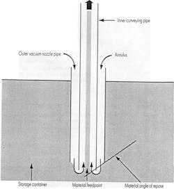
Vacuum nozzle. A vacuum nozzle uses air entering a vacuum conveying system to control the material feed to the system from a storage container. The vacuum nozzle typically consists of an inner conveying pipe inside an outer vacuum nozzle pipe inserted into a storage container. In operation, air enters the system by passing through an annulus between the inner conveying pipe and the outer vacuum nozzle pipe. The air flows toward the material feed point at the inner pipe's end and entrains the material into the conveying system depending on the airflow and how far the inner pipe penetrates beyond the outer pipe (which is determined using the material's angle of repose).
The vacuum nozzle can be any of several shapes but must ensure an adequate air supply to the system's material feed point. The vacuum nozzle is suitable for atmosphere-to-vacuum applications.
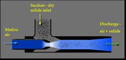
Venturi. A venturi is a constricted section of pipe containing an air inlet, a material inlet and an air-and-material outlet. The venturi creates a vacuum at the material inlet, so material is easily fed from a storage container into the system, with no air leaking out the material inlet. But as the air velocity slows in the venturi, the venturi converts the kinetic velocity pressure into static pressure, establishing a pressure conveying system. The venturi is suitable for atmosphere-to-pressure applications.
Rotary valve. A rotary valve is mounted below a storage container and typically consists of rotating vanes inside a circular cavity with a material inlet at the top and a material outlet at the bottom. As the vanes rotate, a fixed volume of material passes through the material inlet into the spaces between adjacent vanes and is metered through the material outlet.
The valve can function as a feeder, an airlock or a combination feeder-airlock and, with proper valve selection, suits all vacuum and pressure applications within limits. Although various types of rotary valves look alike, they have distinct design differences that affect their application. For instance, selecting a rotary valve feeder when you need a combination feeder-airlock can produce an unsatisfactory pressure conveying system. The rotary valve is the most commonly used feeding device in pneumatic conveying systems.

Lock hopper. A lock hopper is mounted below a storage container and has two chambers separated by an isolation gate or sliding disc. The top chamber has an air inlet and a material inlet. An equalizing valve connects the top chamber to the conveying air source and the bottom chamber, which is open to the conveying line. In operation, the material inlet in the top chamber opens, allowing the chamber to fill with material while the isolation gate or sliding disc between the chambers is closed; then the material inlet closes, and the equalizing valve brings both chambers to the same pressure; and finally, the gate or sliding disc opens, and material drops from the top chamber to the bottom chamber and feeds the conveying system. The gate or sliding disc closes after conveying, and the top chamber is re-pressurized. The lock hopper is suitable for vacuum-to-atmosphere, vacuum-to-pressure or atmosphere-to-pressure applications.
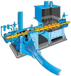
Screw pump. A screw pump is located below a storage container and consists of a compressing screw with a reducing (rather than constant) pitch inside a tubular chamber with a material inlet. The screw pump also has a material outlet and a non-return flapper valve. In operation, material passes through the material inlet and is conveyed between the flights of the screw's larger end. As the screw turns, it advances the material, which compresses the material into the screw's smaller end, forcing air out of the material. The compressed material passing through the outlet prevents air leakage. The non-return flapper valve prevents air leakage when no material is feeding. The screw pump, unlike the screw conveyor, normally operates at a high speed (900 to 1,160 rpm). The screw pump can introduce a fine material into a pressure conveying system without leaking any conveying system air into the storage container and is suitable for atmosphere-to-pressure applications.
Pressure vessel. A pressure vessel (also called a pressure tank or blow pot) is available in many shapes and configurations, each with similar applications. A typical pressure vessel has a material inlet at the top, a vent line at the top and an air inlet. The air inlet is usually located at the vessel top if the material is free flowing and at the bottom or lower vessel sides if the material is fluidizable. Some pressure vessels include air inlets in both locations to handle either type of material. The material outlet is typically at the vessel's center bottom, but in some pressure vessels, the material discharges through a vertical top discharge line or an angled side discharge.
In operation, material fills the vessel by flowing through the material inlet, while the air displaced by the material exits the vessel through the vent line. Next, the material inlet and vent line are closed, and the vessel is pressurized as air enters through the air inlet. If the vessel includes a discharge valve, the discharge valve is opened, and the increasing air pressure inside the vessel moves the material through the material outlet into the conveying line. After conveying, the vent line opens to depressurize the vessel, or the air is allowed to escape through the conveying line.
A pressure vessel is usually required for handling abrasive materials or introducing material into higher pressure conveying systems. The pressure vessel is suitable for vacuum-to-pressure or atmosphere-to-pressure applications.
Jack Hilbert is principal consultant for Pneumatic Conveying Consultants, LLC. He holds a BS and an MS in mechanical engineering from Penn State University, State College, PA, and has more than 48 years of experience in the application, design, detailed engineering, installation and operation of pneumatic conveying systems.
Pneumatic Conveying Consultants, LLC.
About the Author

Jack Hilbert
Principal Consultant at Pneumatic Conveying Consultants LLC
Jack Hilbert is principal consultant for Pneumatic Conveying Consultants, LLC. He holds BS and MS degrees in mechanical engineering from Penn State University, State College, PA, and has more than 50 years of experience in the application, design, detailed engineering, installation, and operation of pneumatic conveying systems.