Hammermill and roll crusher maintenance and operation
Hammermills and roll crushers are widely used in the manufacture and processing of a range of bulk solid products, including foods, pet food, animal feed, aquaculture, ethanol, biomass, oilseeds and others. Regardless of the application, performance will depend largely on the proper sizing and operation of the mill or crusher. This article describes the critical parameters and basic maintenance items for these common size reduction machines.
Fundamentals of hammermill grinding
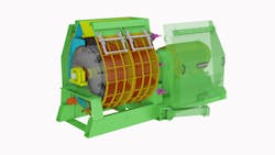
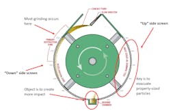
A typical hammermill, as shown in Figure 1, consists of a rotor enclosed in a cylindrical grinding chamber that is encircled by screens. The rotor is mounted with a number of flat metal bars, called hammers, that rotate at high speed through the grinding chamber as material is fed into the mill. The hammers impact the material, breaking up the particles, and the reduced particles then pass through the screens to exit the mill.
Versatility and ease of operation make the hammermill a great candidate for many particle size reduction applications. Keeping maintenance and operating costs to a minimum requires an understanding of the key variables at play in their operation.
Tip speed
Most of the grinding that occurs within a hammermill happens when the material is first impacted by the hammers (Figure 1). The speed at which the hammers are spinning is referred to as the tip speed. Faster tip speeds (>20,000 feet/minute) are more efficient at producing finer grinds. This is because screens with larger hole diameters can be used, which allows more material to leave the grinding chamber. However, faster tip speeds with larger screens will produce more fines and oversized material, which will result in a larger particle size standard deviation. Slower tip speeds with smaller hole diameter screens, on the other hand, will produce a more uniform grind.
Screen area
Hammermills are sized using a ratio of screen area to connected horsepower. For most applications, 14 in²:1 hp is the preferred ratio. Some applications, such as products with a lower bulk density, may require more screen area per horsepower. Hammermills with a ratio of less than 12 in²:1 hp may see premature hammer wear as a result. For this reason, installing a larger motor on an existing mill may not be the best option to increase capacity.
Screen hole diameter
As a general rule, the larger the hole diameter in a hammermill screen, the coarser the grind and vice versa. However, the screen is often not the best variable to change to attain a different grind size. The hammer pattern and tip speed play a larger role in particle size than the screens do. As previously mentioned, larger screens produce a coarser grind at a higher throughput but also result in a larger standard deviation. Screen size affects the larger end of the particle size distribution more than it does the finer end, but at a certain point, application dependent, moving to a larger screen will not result in a coarser grind because of the large role that the hammer pattern and tip speed play in the process.
Hammer pattern
Hammer pattern simply refers to the number of hammers that are installed in the hammermill. Similar to the ratio of screen area to horsepower used to determine motor size, a ratio of horsepower per hammer is used to determine how many hammers should be installed in the mill. Higher ratios will result in a coarse grind, while lower ratios will produce finer grinds. Too high of a ratio (>2.5 hp/hammer) may result in poor hammer life. If the body or pin hole of the hammer are wearing before the hard facing or if there is excessive grooving on the hammer pins, increasing the hammer quantity is a common solution. The most common hammer patterns are in the range of 1.4:1 to 1.9:1 hp/hammer.
Hammer position
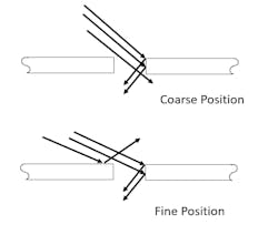
Most hammermill rotors have two different sets of pin holes. The coarse position is closer to the center of the rotor, while the fine position is closer to the outside of the rotor. These positions change the clearance between the hammer tip and the inside of the screens. The main difference between these positions is the exit angle of the material, with the coarse position providing a more direct route for the ground material to exit the grinding chamber, as shown in Figure 2. The coarse position is more energy efficient than the fine setting.
Aspiration
Having an adequate volume of air (called aspiration) flowing through the mill is crucial to an efficient process. The aspiration pulls the ground particles out of the grinding chamber. Too little aspiration keeps the material in the grinding chamber longer, leading to increased fines, premature hammer wear, and reduced efficiency. To calculate the required aspiration (measured in cubic feet per minute [cfm]), the mill’s screen area is multiplied by 1.25 to 1.5, depending on the application. For example, a hammermill with 3,600 in² of screen area will require an aspiration of 4,500 to 5,400 cfm.
Ambient conditions
Ambient temperature and humidity can and will affect hammermill performance. As the material’s temperature and/or moisture increase, the energy required to grind the material increases. Conversely, as the material’s temperature and/or moisture decrease, the material becomes easier to grind. This is why a material may require more energy to grind during hot and humid summer months than during cold and dry winter months.
Basic hammermill maintenance items
The following maintenance steps will help to optimize your hammermill process:
- Replace wear items such as screens and hammers on a routine basis. Energy costs are higher than parts costs. As parts wear, the machine becomes less efficient. Waiting too long to replace wear items may save on parts costs but will cost more in operational costs over the life of the machine. Replace hammers and screens when the cost of lost production due to decreased efficiency is greater than the cost of the replacement parts.
- Change the direction of the rotor rotation frequently to ensure even wear on both sides of the hammers and screen holes. Never spin the hammermill rotor in the same direction for more than 2 weeks.
- Keep foreign material out of the hammermill. Any material not intended to be ground will cause premature wear on the mill’s components. Clean separator magnets frequently.
- Visually inspect the machine each time it is open. Look for uneven wear on parts, which can be caused by uneven feeding across the width of the mill. Another common issue is worn feeder parts that aren’t properly metering the material into the hammermill. Catching an issue before it becomes a bigger problem can save money in terms of parts, labor costs, and downtime.
Fundamentals of roll crusher grinding
In a roll crusher, material is fed from the top into a narrow gap (called the nip) between rotating cylindrical rolls, which grind the material to the desired particle size. Roll crushers can be configured with one, two or three pairs of rolls, depending on the application.
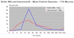
Compared to hammermills, roll crushers can produce a more uniform grind at a much lower operational cost but cannot attain as fine a grind. Figure 3 shows a sieve analysis for a grind from a hammermill and a roll crusher. Each grind produced a distribution with a mean particle diameter of approximately 710 microns, but the distribution from the roll crusher is more concentrated than the distribution from the hammermill.
The main areas to consider with roll crushers are roll size, corrugations, roll speed differential, roll parallel and roll tram.
Roll size
The size of the rolls in a roll crusher is the biggest factor in determining the machine’s throughput, with larger rolls providing greater throughput. However, throughput is not the only factor, and rolls can be too wide. Larger diameter rolls are more advantageous than smaller diameter rolls for three main reasons: a more optimal nip angle, increased roll surface area, and reduced roll deflection.
Nip angle. Larger diameter rolls reduce the nip angle between the rolls and allow the rolls to more efficiently grab the material and pull it down through the rolls.
Roll surface area. More surface area reduces how frequently the rolls must be removed and recorrugated, which decreases labor and downtime costs. For example, a 16x36-inch roll has 33% more surface area than a 12x36-inch roll, so the 16x36-inch roll can process 33% more material than the 12x36-inch roll before requiring recorrugation.
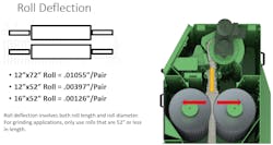
Roll deflection. Roll deflection refers to how much the center of the roll can flex. The rolls are only supported at each end where bearings are attached to the machine’s frame. Deflection is a factor of both roll length and diameter. Rolls that are 16x52 inches can deflect by .0006 inch per roll, whereas rolls that are 12x52 inches can deflect by up to .002 inch per roll and rolls that are 12x72 inches can deflect by as much as .005 inch per roll (Figure 4). For this reason, using a roll longer than 52 inches is not advisable for applications requiring a uniform grind. Rolls longer than 52 inches should only be used when the material will be further processed after the grinding stage. Also, use the largest diameter roll possible to keep the ground material as uniform as possible.
Corrugations
Roll corrugations must be selected according to the materials to be processed and the finished product requirements. Coarser grooving provides longer life and higher capacities but will produce coarse or thicker finished products. Finer corrugations lead to finer products but will reduce capacity and wear out faster. Reviewing roll corrugations as grinding requirements change is an often-overlooked aspect of roll crusher grinding.
Roll speed differential
Roll speed differential is the difference in rotational speed between the two rolls in a pair and is one of the biggest reasons roll crushers produce a grind with a lower standard deviation than hammermills. The differential creates a shearing effect between the rolls that cuts the material rather than squishing it. Using a higher differential will reduce the amount of fines produced, improving the standard deviation. The differential ratio is limited by the size of the sheaves that can fit within the guard of the rollermill. Sheaves are the pulleys on the roll shafts that are connected via belts to spin the rolls at the designated speeds. If the pulleys are too large, they will contact either the other pulley on the paired roll shaft or the frame/guard of the machine. The most common roll speed differential in roll crusher grinding is 1.5:1.
Roll parallel and roll tram
To maximize roll life and achieve consistent end-to-end performance, each pair of rolls must be parallel and tram, which means level with each other on a horizontal plane. If the rolls operate out of parallel, they will grind the material fine at one end and coarse at the other and will also wear unevenly. The same is true for rolls out of tram. Normally the tram adjustment will only be set when the operated rolls are changed or in some significant upset condition (such as lost elevator buckets and bolts appearing in the nip of the rolls).
When the rolls are not parallel or tram, material tends to "drift” in the nip of the rolls toward the more open end(s). This excess material may begin to “pile up” in the nip of the rolls and cause accelerated wear. Trying to make a fine grind when out of parallel or tram may cause the “close” end (or center of the rolls if out of tram) to make metal to metal contact. You can routinely check the roll parallel by using a feeler gauge when the machine is open or by taking samples from each end of the rolls to compare grind sizes.
Balance between roll pairs
In double- or triple-pair machines, it is necessary to balance the work being done between the pairs of rolls to avoid premature wear on one of the roll pairs. When properly managed, each pair of rolls will wear at approximately the same rate. By using a “staggered” corrugation on the fast and slow rolls (with coarser grooving on the fast roll) all four (or six) rolls will be ready for recorrugation at the same time. Changing all rolls at once is usually the most efficient use of the time and effort required to make a roll change.
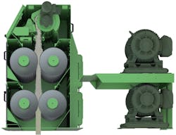
Rolls must be operated in a way to avoid having the material pile up in the nip when the mill is running at full capacity. This is not normally a problem when the rolls are in good condition, as the corrugations will easily pull in the material and the motor load will limit the throughput. As the corrugations, in the top rolls especially, become dull, they will lose their effectiveness at pulling the grain in, and material may begin to pile up in the nip. This condition must be avoided since the material slipping in the roll nip will greatly accelerate roll wear. If the mill capacity decreases, or if the motor load does not go up when the feeder speed is increased, it is very likely that the material is not passing through the top pair of rolls. To maximize capacity and extend roll life, open the top pair of rolls slightly and/or reduce the feed rate to eliminate accumulation in the nip of the top rolls. If the finished product is too coarse, close the bottom rolls to obtain the desired finished particle size (Figure 5).
Basic roll crusher maintenance items
Perform the following checks frequently for optimal roll crusher performance:
1. Check roll parallel.
2. Check belt tension and alignment.
3. Clean separator magnets.
4. Visually inspect the rolls for abnormal, uneven or premature wear.
5. Check cheek plates and roll seals to ensure that all the material is passing through the roll nips. Cheek plates contour to the ends of the rolls to prevent material from passing around the rolls at the ends, while roll seals are plates mounted at the top of the rolls to prevent material from passing over the rolls at the top.
Doug Kitch is technical sales supervisor at CPM Americas and can be reached at [email protected] or 319-232-8444.
CPM Americas
About the Author

Doug Kitch
Technical sales supervisor at CPM Americas
Doug Kitch is technical sales supervisor at CPM Americas and can be reached at [email protected] or 319-232-8444.
