Screen selection criteria for milling machines
Bulk solids processing often includes one or more size reduction steps to improve a material’s value or functionality. For example, granular sugar can be pulverized into a powder, improving texture for use in icings, while scrap wood can be shredded then reduced through one or more hammermilling steps to manufacture secondary products such as oriented strand sheeting or particle board.
The market offers a variety of machines for size reduction, and many of them utilize a screen to aid in the size-reduction process. Typically, this screen is chosen by the original equipment manufacturer based on application experience and testing. This article will discuss the various aspects of screen selection along with their effect on mill performance, providing end users with a foundation to make informed choices when optimizing their equipment.
The sizing screen’s role
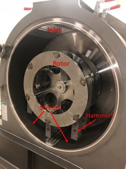
While milling machines vary from one type to another, the screens they use serve a common purpose: 1) to retain material in the grinding zone and 2) to provide additional cutting/impact surface. A hammermill, for instance, includes a grinding chamber defined by a rotor fitted inside one or more screens (Figure 1). As the rotor spins, hammers affixed to support pins at its circumference extend outward, striking particles introduced through the machine’s inlet.
The screens are fitted in close tolerance to the hammers, providing a web into which accelerated particles collide. These secondary collisions cause more destruction and decelerate the particles. From here, smaller particles find their way through the screen’s apertures while larger ones recoil back into the hammers’ path. The process repeats until all particles are small enough to exit through the screen with high probability.
In this manner, sizing screens play a vital role in determining the particle size of a ground product. This affects the mill’s performance by altering retention time and the amount of work the mill must perform.
Common screen types
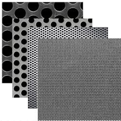
Three main types, or profiles, of screens are used in milling machines: 1) round hole screens, 2) slotted or herringbone screens and 3) conidur screens (Figure 2).
Round hole screens are by far the most common. These screens are created by stamping circular holes into a steel sheet. The holes are arranged in rows, with the holes from one row offsetting the holes in adjacent rows. Round hole screens are available in a wide variety of sizes and suitable for grinding most free-flowing bulk solids.
Slotted and herringbone screens are manufactured by stamping elongated holes into sheet steel. The pattern of slotted screens is like that of round hole screens, where the slots align end to end in rows, with adjacent rows staggered from one another. The holes of a herringbone screen form angles to one another, with adjacent rows aligned. Both types are good for sticky, high moisture and fibrous products due to the larger hole area.
Unlike the other screen types, conidur screens are made by raising the surface of the steel sheet. The resulting shape and surface profile resembles a “rasp” or “cheese grater.” Because of the tooling and methods used, conidur screens are available in smaller hole sizes than other types while maintaining rigidity in the material used to make them. For this reason, they are commonly used for finer grinding of products such as salts, sugar and grains. In addition, their rough surface works well to help reduce harder materials.
Screen hole size
By far, the most important feature of a screen is hole size, which refers to the size of opening through which a particle will pass. The larger the hole, the larger the particle size output. Remember that a sizing screen’s purpose is to provide retention time and impact surface, not to classify the material.
Therefore, hole size is chosen to match the mill’s ability and the product’s friability (a term used to describe a particle’s brittleness, or ability to shatter upon impact). For highly friable products, such as sugars, salts and grains, a hole size 8-10 times the largest desired particle is practical. For products with average friability, such as resins, minerals, chemicals and clays, a screen hole size 5-8 times the largest desired particle will provide satisfactory results. For harder, less friable materials, such as wood, grain hulls, shells or fiber, a hole size 2-5 times the largest desired particle size is more common.
It is also possible to pick a hole size that is too small, so that the mill cannot make the particles fine enough to pass through. A small screen can also hold the product too long, overworking it to the point that it softens or melts, creating a plug inside the machine.
Open area
The second most important screen attribute is the open area. A manufacturer calculates open area as the percentage of screen surface occupied by holes. In many cases, two or three open areas are available for a given hole size. This is accomplished by altering the centerline distance between holes (Figure 3). Typical open areas range from 20-60% for perforated screens and 5-15% for conidur styles.
Open area can benefit or hinder capacity by altering the probability for accelerated particles to pass. For instance, a higher open area screen will have less webbing between holes, increasing mill capacity. However, the screen will also be weaker, so the mass of incoming particles should be considered through trial and error.
In cases where more than one open area is available, it is best to choose the least open area that will achieve a capacity requirement.
Gauge
Gauge refers to the thickness of steel used to make the screen and is indicated by a whole number. The higher the gauge number, the thinner the screen. For instance, a 10-gauge screen is 0.1345-inch thick, while a 12-gauge screen is 0.1046-inch thick and a 16-gauge screen is 0.0598-inch thick. Gauge sizes are nominal, varying between materials and from one manufacturer to another.
Like open area, manufacturers also provide two and sometimes three gauges for a given hole size. In general, as the screen becomes thicker, the open area will decrease due to increased stress on the sheet during the stamping process.
Thinner screens are better able to handle products with higher moisture, fat or oil content. The thinner hole profile results in less friction as cohesive particles are accelerated through the holes.
Thicker screens can benefit applications with a large unsupported span. This is particularly true in bigger mills. In this case, the screen is stronger and better able to resist deformation from the product impacting it.
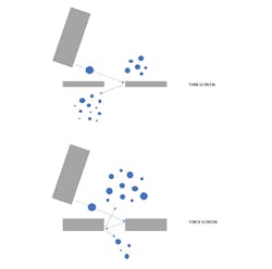
While a thicker screen is stronger, it can also reduce output as the hole will appear smaller to the approach angle of particles. As the particles rebound off the trailing side of the hole, they can rebound into the leading edge or back into the machine, reducing the output (Figure 4). In this case, the thicker profile can be offset by choosing a larger hole size.
Hole orientation
Hole orientation pertains to the way the round holes are arranged on the sheet. Manufactures offer two styles: 1) straight hole perforations and 2) staggered perforations.
The orientation of holes in a finished screen affects capacity and wear characteristics. Straight hole perforations should be avoided because, no matter their direction of installation, there will always be continuous rows of webbing to impede the exit of particles from the mill (Figure 5, left).
A staggered profile sheet that is cut and formed square to its long edge will also result in continuous rows of webbing in the direction of flow (Figure 5, center).
In contrast, a properly staggered profile will result in holes with significant overlap between rows (Figure 5, right). This provides the highest probability for on-size particles to exit the mill once impacted and accelerated. Staggered holes can be achieved cutting the screen to size such that rows run perpendicular or at an angle to the direction of flow.
Face orientation
The final consideration for screen manufacture is face orientation. For all flat profile sheets that are stamped, the tooling will create a round over on the entry side of the sheet and a sharp corner or burr on the exit side.
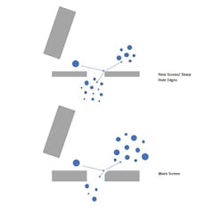
Screens manufactured and formed with the sharp or burred edge facing the flow of particles will result in greater performance. The approach angle of particles against the trailing edge of a sharp hole can enhance cutting action and aid in size reduction, allowing more product to exit faster.
In contrast, a screen manufactured with the rounded side facing the flow of particles can result in more “skipping” along the holes’ trailing edges. This can result in more residence time and reduced capacity. The same is true for screens where the holes are rounded due to wear (Figure 6).
Final thoughts
A sizing screen is often the most frequently replaced component in a milling machine. When it is time to replace a screen, consideration can be made for what is working well and what needs improvement. Are the screens providing suitable life? Is the screen always failing in a common area? Are the particle size objectives being met? Is a smaller hole size practical for the abilities of the mill?
Reviewing past performance and future goals with your mill supplier can ensure that the best screen selection is made for each application.
Darrell Malczewski ([email protected]) is the Midwest regional sales manager for Prater Industries, a global supplier of airlocks, size reduction and screening/separation equipment. His 25 years of bulk material handling experience include various roles with Prater, including test lab manager, technical field services, airlock product manager and currently regional sales.
Prater Industries
About the Author

Darrell Malczewski
Midwest regional sales manager for Prater Industries
Darrell Malczewski ([email protected]) is the Midwest regional sales manager for Prater Industries, a global supplier of airlocks, size reduction and screening/separation equipment. His 25 years of bulk material handling experience include various roles with Prater, including test lab manager, technical field services, airlock product manager and currently regional sales.
