Installing a radial ball or roller bearing properly is critical to achieve the full service life of the component. Improper mounting methods that take advantage of shortcuts, such as using a hammer or a torch, will result in premature failure or a potential safety hazard. This article addresses proper bearing installation tips, specifically the installation of non-housed bearings, as opposed to housed bearing units such as a pillow block.
It is imperative that all safety issues have been addressed, enough time has been allotted for the job and the procedure is understood by all, before the work of bearing installation begins. An investment in proper tools, procedural training and time, will result in definitive cost savings and prolong the life of the bearing and the machine in which it is mounted. The price of the bearing and the man-hours to do it right are miniscule compared to the overall cost of downtime, the initial price of the machine, potential ancillary damage and, of course, the harm that may occur to an installer or machine operator. “Do it right the first time” is not just cliché; it should be mandatory and part of the maintenance culture in your plant. All required personal protective equipment (PPE) should be worn throughout these processes.
Mechanical removal, installation and methods
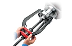
Removing a failed bearing safely and properly is step one. Pullers and presses designed for that purpose are the best options for three reasons: safety, saving time and minimizing the damage to the shaft and housing during the process. Two- and three-jaw mechanical pullers pull evenly on the outer ring as the threaded post is tightened, which is centered on the end of the shaft (see Image 1).
Another type of removal tool is the separator or knife type that has two plates placed behind the bearing. Heavy-duty pullers are made with hydraulic-assist rams, allowing for ease of removal. If the bearing is removed using a high-speed, cut-off tool, and if it is used carelessly, the shaft and housing may be damaged. Although size and space limitations sometimes dictate the necessity of this method, any subsequent nicks and gouges on the shaft or in the housing result in metal removal. This metal removal, in turn, changes the all-important dimensional tolerances and proper fitting of the bearing. Avoid open flames or the making of sparks during the process if at all possible.
It is generally not recommended to reuse a bearing that has been removed from service, but it is recommended that the bearing be examined after removal for cause of failure. Stress over time may result in damages that cannot be seen by the naked eye. It also requires some fault analysis education and experience to determine the cause and nature of the failure. The only time a bearing may be reused is if it has been sent back to the manufacturer for cleaning, inspection, measuring, regrinding and reassembly. This is not cost-effective with smaller bearings.
Careful handling of the replacement bearing while in storage or during the installation process is imperative. Clean, dry, ambient and vibration-free storage conditions are best. Do not unwrap the bearing until ready to install it. Do not wash out the factory lubricant unless required to do so because of special lubrication requirements. Cleanliness is a way of life, for the mechanic and the bearing as well.
Making sure that an exact replacement is used is important. There are two ways to identify a mechanical component: taking measurements and/or checking for a part number. Reputable manufacturers mark the rings of a bearing with a part number. This number can be referenced in a catalog that lists the dimensions and tolerances of the rings. A rough measurement can be obtained using a slide caliper. For exact measurements, a calibrated, certified, Vernier micrometer that measures to within 0.0001 inch is recommended.
The shaft and housing should be clean and free of gouges and burrs. Although emery paper is commonly used in industry for this purpose, keep in mind particles loosened from the backing paper may contaminate the bearing. Preferably, industrial Scotch-Brite pads should be used to clean the shaft or housing of any fretting or corrosion. A light machine oil may be used to eliminate any moisture or acids. Cleanliness is imperative throughout the process. Remember, the size, shape and condition of the shaft and housing have a direct effect on the life of the replacement bearing.
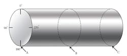
It is imperative to measure and check the shaft and housing bore to ensure it is within the recommended dimensional tolerances for the application and bearing size. Calibrated measuring tools such as a micrometer or slide caliper should be used. An eight-point measuring method is recommended for both the shaft and housing (see Figure 1). This involves four measurements at various locations to determine that the shaft and housing are not elliptical and the sides are parallel. Bearing installation guides and machinist’s handbooks will list the various types of fits and the exact dimensional tolerance for both the bearing rings, shafts and housings. If they are not within the suggested specifications, a diminished bearing life will occur. An oversized shaft or undersized housing will reduce the required internal clearance in the bearing. This clearance is necessary to make for free rotation of the rolling elements, lubrication film and the metal expansion that will occur because of thermal changes. Fits that are too loose will cause the bearing to walk or creep, pulling metal, which inevitably ends up in the bearing. Remember, measure prior to mounting.
The three general types of fits are: interference or tight, line-to-line, and clearance or loose. The fit is determined by the nature of the application, load, size, type of bearing and which ring is rotating.
The level of force required to properly mount a bearing is determined by the type and degree of press fit. In most applications, whichever ring is rotating will have the press fit. For example, an electric motor’s shaft rotates with the rotor. Therefore, the inner ring of the bearing will require a press fit and the outer ring will be a line-to-line or a clearance fit.
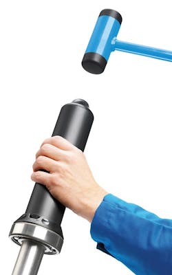
Bearings less than 50 millimeters (mm) in diameter may be mounted by using a bearing driver if the rings are installed with a light interference fit. Driving tools consist of a metallic tube, polymer impact rings and a dead blow hammer (see Image 2). This type of tube driver can be used with bushings and oil/grease seals. It is important to use the proper sleeve and impact ring size and ensure the bearing does not become cocked while being seated.
An arbor press is a safe method for removal and installation. The press should be bolted to a sturdy workbench or the floor. A rack and pinion along with a long handle are used to provide leverage. Pressing down on the handle lowers the rack. Never attach a pipe to the handle. Apply pressure slowly. A slotted plate, commonly referred to as the anvil, is used to support the machine piece and allow for through access of the shaft. Ideally, use only accessories designed for the press. The proper blocking of the bearing rings is essential as is the alignment and squaring of the workpiece for effective even force. When using a press, make sure that the bearing rings are blocked correctly so that the mounting forces are not transmitted through the rolling elements. These forces will cause dents in the raceway paths, known as true brinelling.
A hydraulic press is a useful and efficient machine to remove and mount bearings but its use comes with several caveats. It is imperative that the maintenance technician be given safety and proper use training. The hazards are numerous for the operator and there is a potential to damage the associated machined components. These presses are usually rated in tons of pressure. Keep your hands clear, identify the start/stop button and wear PPE. The same considerations that apply to the use of hand presses are applicable to the use of hydraulic presses. Squaring and alignment of the workpiece, proper blocking of the bearing and shaft, and slow, even pressure are required. Lower the ram slowly and observe where the force is being applied. The same person should insert/set up the work and operate the press. Do not exceed the working load limit of the press.
Thermal removal, installation & methods
Lowering or raising the temperature of the bearing, shaft, and/or housing within prescribed limits is another method to remove and install bearings. All of the cautionary notes mentioned for mechanical removal methods also apply to thermal methods. The shaft and housing should be clean and clear of nicks and burrs. Time must be allotted to measure and confirm that the shaft and housing are within the recommended dimensions. If the shaft or housing is not within the recommended tolerances, it should be replaced. Although the use of bonding agents may temporarily buy some time, bearing mounting compounds do not replace the requirement for a good dimensional fit.
The use of liquid nitrogen or dry ice to lower the temperature of steel components should only be used when there is an extreme interference fit. During winter months in northern climes, it is common for technicians to place large-diameter shafts outside overnight, then heat the bearing in the morning and assemble them together. Remember, a byproduct of this process may be the formation of water due to rapid temperature changes and the relative dew point. Water on steel equals rust.
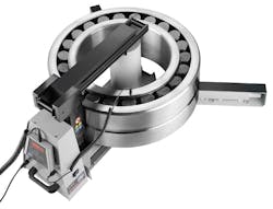
There are a variety of bearing heaters such as the cone type, heated plates, pizza oven and the all-too-common oil bath. All of these types have two things in common: They are slow and usually dirty. For the mounting of bearings onto a shaft, the best means is to use a modern bearing induction heater (see Image 3). They are safe, fast, efficient and clean. Induction heaters are available in various sizes, with most being portable by hand or placed on a cart. They also can be used to heat other components such as coupling hubs and bushings.
Bearing induction heaters produce a strong, alternating, magnetic field to induce eddy currents in the metal. These currents cause rapid heating of the ring. It can be compared to a transformer using a primary coil with numerous windings, and a secondary coil with a few windings (the bearing). The secondary coil will deliver a low voltage at high amperage. The bearing acts as a short-circuited, single-turn, secondary coil through which passes a low alternating voltage at high amps. The result: The ring closest to the bar is rapidly heated. One of the byproducts of this process is magnetization. Modern heaters have an automated demagnetization cycle at the end of the process. Remember, the temperature probe should be placed on the inner ring for expansion to accommodate a press fit to shaft. The recommended temperature setting is 110°C or 230°F. The operator has complete control of the settings.
Bearing installation reminders
- Wear your PPE.
- Careful handling and cleanliness is important.
- Avoid steel hammers or sparks if at all possible.
- Inspect the shaft and housing. Remove burrs.
- Measure, measure and measure again.
- The fit matters.
- Use identical replacements.
- Avoid overheating.
- Use the right tools.
- Be safe, think safe, do it safe!
Conclusion
Installing a radial ball or roller bearing properly is critical to achieve the full service life of the component. For proper bearing installation to occur, it is imperative that all safety issues have been addressed, enough time has been allotted for the job and the procedure is understood by all before the work begins.
Richard R. Knotek is a Technical Training Specialist with the Motion Institute, a division of Motion Industries. He has worked 43 years with Motion Industries, holding a variety of positions including driver, inside sales, operations manager, salesperson, branch manager and product specialist. A former adjunct instructor with Northern Michigan University’s Industrial Maintenance Program, Knotek is also the published author of Mechanical Systems & Principles (ISBN 0-13-049417-8). For more information, visit motionindustries.com or the video channel MiHow2.com, which features educational videos including bearing installation tips.


