Top 10 tips for specifying & using variable frequency drives
Variable frequency drives (VFDs) have been used to control the speed of three-phase alternating current (AC) induction motors since the 1980s. They also provide adjustable acceleration and deceleration, overload protection and start-stop control of motors. These and other features make VFDs a good choice for fans, blowers, centrifugal pumps, mixers, agitators and conveyors – which require variable horsepower and torque – and for applications in which energy is saved by operating at reduced speed.
VFDs convert single- or three-phase AC input power to direct current (DC), and then invert it back to three-phase AC output power. Before it is converted to the output, the VFD varies the frequency and voltage of the inverted power, allowing it to control motor speed based on the setpoint, which is either set at the VFD or more commonly sent to it by the automation system.
A VFD is often not the best choice for a constant-speed application requiring controlled stops and starts because the electronic conversion of AC to DC to AC results in an efficiency loss of about 4 percent. However, if a variable motor speed is needed, the benefits of a VFD are typically more than sufficient to overcome the efficiency loss. To realize these benefits, consider the top 10 tips for specifying and using VFDs described in this article.
1. Understand & use the benefits & features
The benefits of using VFDs include energy savings, adjustable motor speed and torque, reduced motor inrush when starting, and controlled stopping and reversing. Probably the biggest benefit is reduced energy consumption when operating devices such as blowers, fans and centrifugal pumps at slower speeds.
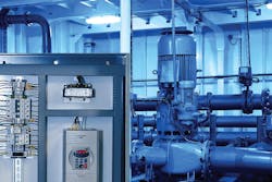
For example, reducing the speed of a blower to 50 percent reduces the air flow by 50 percent as well, but cuts the power requirements by 87.5 percent. Required fan, blower and centrifugal pump power is proportional to the cube of motor speed, saving significant energy at lower speeds (see Image 1).
The VFD’s ability to vary motor speed allows the optimization of the work required by a machine or process because only the needed speed is provided. This contrasts with running the motor at full speed and throttling the output, which is inefficient, decreases motor life, and increases maintenance for the motor and the throttling equipment.
Torque can also be limited to protect machinery or product from possible damage. These adjustments can be made automatically using a programmable logic controller (PLC) or other controller, or manually using a keypad or potentiometer on the drive.
The VFD can reduce motor starting currents that can be more than eight times the full-load current of a motor. With larger motors, this full-load starting places significant demand on the power distribution system. These high demands can result in a voltage dip or voltage sag when the motor starts at full voltage. A controlled acceleration start, provided by a VFD, addresses this issue.
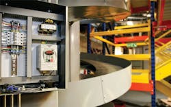
With VFDs, controlled acceleration reduces starting current and extends motor life. This is especially true in applications that require frequent starting and stopping. Additionally, the VFD eliminates the need for a reversing starter. The controlled acceleration and deceleration provided by a VFD reduce equipment wear and tear and related breakage and loss (see Image 2).
2. Choose the VFD based on load size
Sizing VFDs often requires more than just matching the horsepower rating to the motor. The operating profile of the load it controls must be considered. Constant or variable loads, frequent starts and stops, or continuous operation must also be considered when selecting the equipment.
The torque and highest peak current at any time during operation should be determined. This starts by confirming the motor nameplate full-load amps (FLA). However, rewound motors may have higher FLAs than what is listed on the nameplate.
The VFD should be sized based on peak torque demand instead of just horsepower. Under certain conditions, the motor may demand more power and/or torque, and oversizing may be necessary when dynamic loads or impact loading creates temporary overload conditions. In these and other high-demand situations, the VFD must provide enough current to ensure acceptable motor performance.
For example, more power from a VFD is required to provide additional breakaway torque to start a fully loaded conveyor. While many VFDs can operate for 60 seconds at 150 percent overload, higher overloads may be seen for short durations. Whether the overload duration is short or long, an oversized VFD may be required to provide the headroom required by the application. Even high-altitude installations may require oversizing because less air cooling of the VFD is available.
3. Determine braking options
A VFD may also need a little help when decelerating a load. While it can stop moderate inertia loads, high-inertia loads may cause an overvoltage condition in the drive. For quick deceleration of heavy loads, an external dynamic braking resistor should be considered.
The braking resistor allows the VFD to produce additional braking torque by reducing the voltage generated by a decelerating motor. Without the braking resistor, typical VFDs provide approximately 20 percent braking torque. The external braking resistor can significantly increase the VFD’s braking torque for the fast deceleration of heavy loads, and reduce the heat in the drive caused by frequent starts and stops.
4. Interface to the VFD
VFDs are controlled by either hardwired, discrete and analog input/output (I/O); or by digital communications. The discrete inputs to the VFD, usually outputs from a PLC, are used to start and stop the drive, although manual pushbuttons and selector switches can be used as well.
Other configurable drive inputs include jog, fault reset, accelerate/decelerate select, preset speed (step) selection, proportional-integral-derivative (PID) control and others. Discrete outputs from the VFD include fault present, frequency attained, non-zero speed and local/remote indication. Some higher-end drives also include frequency outputs for speed reference. A drive’s analog input typically accepts a speed command from a PLC or remote potentiometer. These analog signals are typically 0 to 10 volts DC, 4 to 20 milliamps or something similar.
The drive’s analog output, where available, also has the same signal levels. The analog output can provide a speed reference signal proportional to the motor’s speed. This speed signal can be used to command downstream VFDs’ speeds in a master-follower setup. This configuration can synchronize several VFD motors’ speeds. Alternatively, the analog output can provide analog speed, current and torque signals to the PLC.
5. Understand digital communication options
Digital communication protocols allow commands and information to be communicated between a PLC and the VFD across a single cable, as opposed to the many wires and cables required for hardwired I/O. Protocols range from simple serial interfaces such as Modbus RS-232/RS-485 to more advanced Ethernet and fieldbus communication options such as EtherNet/IP.
These communication interfaces allow the VFD to be controlled by a master device, such as a PLC or other advanced controller. This interface can eliminate the need for hardwired discrete and analog I/O, and enables the monitoring of the drive’s speed, current, fault and other parameters. A serial, RS-232 connection to a drive works well for single drive applications located near the PLC. If multiple drives are needed, an RS-485 network can handle multiple drives in a daisy-chain, multidrop configuration and stretch the communication distance up to 4,000 feet.
An Ethernet interface provides higher performance in terms of speed, bandwidth and network configuration options. Multiple drives can be controlled by a single PLC using industrial Ethernet protocols such as Modbus TCP/IP or EtherNet/IP, simplifying VFD wiring and providing an easy way to remotely configure drives.
6. Apply the right control mode
The application often determines the type of VFD control mode: volts-per-hertz (V/Hz), sensorless-vector or closed-loop. V/Hz controls the ratio between voltage and frequency to vary the motor flux, which supplies the operating torque to the motor. V/Hz drives work well for most applications, such as fans and pumps.
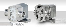
Sensorless-vector VFDs are known for their accurate speed control across a wide speed range without the need for encoder feedback because they work well in open loop. A closed-loop VFD uses encoder feedback for accurate speed control by monitoring actual motor speed and slip information. Sensorless-vector and closed-loop VFDs provide excellent speed regulation, providing tight speed control for paper mills, web handling, printing presses and other converting applications (see Image 3).
7. Define motion profiles
How a VFD’s motion profile is configured depends greatly on the application. Motion profile parameters include motor speed, acceleration, deceleration, ramp linearity, torque control, braking and PID. Most VFDs in the market include these parameters, although PID may only be available on more advanced drives.
These parameters can be accessed and programmed using the operator keypad and display or via digital communications. Careful review of the manual will help users understand these parameters and ensure proper installation, setup and control.
8. Outline the installation requirements
Following the installation requirements is important because VFDs generate significant heat while operating. Frequent starting and stopping can cause the drive to heat up an enclosure, requiring ventilation to keep the temperature within drive specifications. The manual provides information to help calculate the expected heat output of the VFD during different operating conditions. A standard induction motor can overheat if run at low speed for an extended period. If low speed operation is required, an inverter-duty-rated motor should be specified.
9. Specify operation parameters
From a control standpoint, the VFD should not be routinely stopped by opening a contactor on the input voltage supply because this reduces its operating life. This should only be done for emergency stop purposes. The drive I/O or communications should control the start-stop in all other instances. These and many other installation and operation procedures are outlined in the manual and should be followed carefully, and the VFD supplier should be contacted with any questions.
10. Handle noise & harmonics
VFDs generate electrical noise and harmonics that may cause damage to motors, equipment, transformers and power wiring. Fortunately, filters and line or load reactors can minimize many problems. Most VFD installation instructions recommend the use of passive harmonic filters, such as AC line reactors and chokes. These devices reduce harmonics and protect VFDs from transient overvoltage on the line side of the drive.
On the line side, active harmonic filters invert the harmonic current waveform and feed it back to the line to counteract the noise generated by the VFD. On the load side, a load reactor protects the motor cable insulation from short circuits and reflective wave damage. Including these reactors in all applications with standard inductive motors and in any application where the VFD-to-motor distance exceeds 75 feet are good design practices.
Joe Kimbrell is product manager, Drives, Motors, and Motion Control, for AutomationDirect. He may be reached at [email protected].
