Reducing the risk of dust explosions in mills and size reduction equipment
Many process industries, including the chemical, food, plastics, power, wood, metallurgical, agricultural and pharmaceutical industries, use mills to reduce the particle size of bulk solid materials. Historical data points to milling and size reduction equipment as often being involved in combustible dust explosions in processing plants. A single incident can damage equipment, stop production, and put workers at risk. Most milled materials pose an explosion risk unless the mill is processing a non-combustible material such as sand, for example. Mills inherently increase the risk associated with handling powders, as smaller particles are easier to ignite and provide more surface area to generate a more impactful deflagration. This article will focus on how to protect hammermills or other fine-grinding mills from explosion risks; however, some of the advice may also apply to other milling equipment, such as ball or pellet mills.
Milling energy and ignition
One complicating factor in protecting mills is that the action of milling itself requires high kinetic energy and generates pressure fluctuations during normal operation. This means that protection equipment, such as explosion vents and suppression systems must be specified to release at a certain pressure level to avoid unwanted activations.
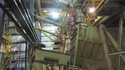
A hammermill reduces material down to a maximum particle size, with material entering through an inlet near the top of the mill and passing through a grinding zone, where the particles are impacted repeatedly by hammers mounted on a rotating shaft. Once the particles are small enough, they pass through a screen mesh or plate with specifically sized openings that surrounds the grinding chamber. The resulting material’s particle size distribution is determined by the tip speed of the rotating hammers. The reduced particles then exit at the bottom of the hammermill via either a pneumatic or mechanical discharge system.

Before material enters the mill’s grinding zone, a magnetic separator is often used to detect and remove tramp metals. It is not uncommon for a hammermill’s feed material to include tramp metals, particularly when milling is an early step in the manufacturing process, such as when milling harvested grains or wood-based materials, for example. Tramp metal that enters the grinding zone can create sparks and ignite the dust in the mill.
Sometimes even non-sparking tramp metals can contribute enough heat through friction to ignite the dust in a mill. Whichever mechanism ignites the dust, the ignition can start a fire and potentially lead to an explosion and subsequent secondary explosions. Ignited material could also enter downstream equipment such as a dust collector or filter-receiver or surrounding plant areas. Dust (fuel) inside a vessel, on surfaces or in the air can worsen a deflagration and potentially cause more damage.
Mill discharge options and protection
A hammermill can be set up for pneumatic or mechanical discharge, and the discharge type impacts fire and explosion protection options.
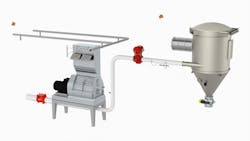
Pneumatic discharge uses a pneumatic airlift system, in which discharging material drops directly into a negative-pressure, dilute-phase pneumatic conveying system that draws the material to either a cyclone or filter-receiver for collection. Figure 1 shows an example of this configuration with explosion protection options, including flame detection, an isolation flap valve, flameless explosion venting, an infrared detector, an isolation pinch valve, pressure detection and an explosion-proof rotary airlock valve.
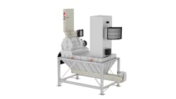
Mechanical discharge uses an elongated hopper or plenum to receive the discharging material. The plenum directs the material into an attached screw conveyor, which then feeds the material into an explosion-proof rotary airlock. The airlock serves to isolate the mill and plenum area from downstream equipment. The plenum arrangement over the screw conveyor creates a small area where material can build up without backing up into the mill itself. This area can give operators time to find and solve mill issues that would cause a backup and prevents other issues such as overheating that could happen if there were no area for material to be staged outside the mill itself. Figure 2 shows an example of this configuration with protection options, including spark detection, flameless explosion venting and a chemical suppression system.
Both pneumatic and mechanical discharge systems must account for the hammermill’s operational needs. The hammermill requires continuous airflow through the mill to keep the milled material from clogging the screens. Pneumatic discharge relies on airflow to draw the material into the conveying line, which ensures sufficient airflow through the mill. For mechanical discharge, adequate airflow is achieved by placing a dust collection system at the end of the plenum opposite the hammermill discharge. The dust collector draws just enough airflow to keep the screens in the mill clean while still allowing the discharged material to drop via gravity into the screw conveyor at the base of the plenum.
While the addition of the plenum has advantages, it also creates an additional confined space for airborne dust and is subject to explosion protection requirements similar to those of a dust collector.
Milling equipment maintenance and plant housekeeping
Proper maintenance of milling equipment is key not only to consistent processing to produce the highest quality product, but also to minimizing factors that can lead to serious explosion hazards. As mentioned previously, foreign objects such as rocks, screws, or other items entering the milling chamber can generate friction and sparks, but excessive wear to the mill’s internal components can also create ignition hazards. Hammer wear or breakage can perforate the screen and/or introduce metal into the discharge area and downstream equipment. Poor maintenance can also lead to overheated bearings, additional unwanted friction and other issues that could contribute to ignition. Periodic hammer inspection and replacement along with regular lubrication of bearings, motors and couplings can help prevent dust ignition in the mill and ensure smooth operation.
While dust is always present inside the mill, good housekeeping and maintenance in the areas outside of the milling equipment is critical because an ignition event inside a mill may release flame or pressure. For example, if the mill is equipped with an explosion vent, the flame could impact surrounding areas, or a layer of dust can provide additional fuel that could lead to a secondary explosion (depending on the volume of the room). If there are conveyors nearby, the burning material or heat could interact with the material being conveyed and spread to another plant area or trigger secondary explosions. As a result, nearby areas and surfaces must be kept free of dust buildup through the use of a central vacuum system, sweeping, or other manual cleaning method.
Key dust testing characteristics to consider
Before you can select the correct fire and explosion protection options, you must first test your dust to determine its combustion characteristics. Typically, dust testing is part of the dust hazard analysis (DHA) process, which is required by NFPA 652 Standard on the Fundamentals of Combustible Dust, as a way to identify and analyze combustible dust hazards in a facility. Since any facility with a dry mill must complete a DHA, testing of dust samples from your milling operation may have already been completed, but if your raw material has changed, new dust testing should be done.
When milled, dry material typically becomes more combustible, so testing the finest fraction of material in the milling process will yield the most relevant test results. Three key material characteristics to note are the dust’s deflagration index (KSt), maximum explosion pressure (Pmax) and minimum ignition temperature (MIT).
KSt is a measure of how fast pressure increases during a dust explosion. A dust’s KSt is generally measured in lab tests by making a sample of the dust (powder) explode within a pressure-resistant vessel. Based on the test result, the powder can be classified as St 1, St 2 or St 3, with a higher KSt equating to a faster deflagration rate (explosion strength) than a lower KSt.
Pmax is the maximum explosion pressure generated when the dust is ignited in a laboratory setting. This characteristic is used in conjunction with KSt to determine the required size of explosion venting and explosion suppression systems.
MIT indicates the minimum temperature of a hot surface required to ignite a dust cloud of a specific material. A mill’s internal components or other surfaces could heat up and come into contact with your dust, so understanding the dust’s temperature limitations can help when setting up monitoring equipment.
After testing, you can compare your dust’s characteristics to the specifications of fire and explosion protection products and design a system that will ensure adequate explosion protection.
Mill protection options
Three general approaches are used to minimize explosion risk in a mill: containment, chemical suppression and venting. In any of these approaches, the mill’s three connection points — the air intakes, the material inlet and the material discharge — require explosion isolation, such as an NFPA-compliant rotary airlock valve, explosion isolation flap valves, explosion isolation pinch valve, chemical isolation, or a flame-arresting device. Also, infrared (IR) detection for spotting heat and a spark detector should be installed below the grinding zone to both stop operation and extinguish any ignition activity in the mill system.
Containment. Building the mill and associated rotary airlock valves to containment standards using thicker metals and robust construction can help keep flame and pressure inside the mill. The construction process must account for the maximum explosion pressure the material could generate. If you take this route, then the filter-receiver should either be considered part of the containment system or protected separately by IR detection, a fast-acting valve and explosion venting or suppression. Remember that burning material leaving the mill via discharge can propagate the incident to other equipment or plant areas if proper isolation, suppression and other safeguards are not in place in addition to containment.
Chemical suppression. Suppressing sparks or flames with a dry chemical extinguishing agent protects the mill from a deflagration. Suppression systems include a controller, detectors and suppression bottles. Pressure and optical detectors detect a developing deflagration at an early stage and trigger the injection of chemical suppressant into the process. Chemical suppression can provide an economical design advantage on larger milling systems, indoor mills or milling systems with limited space to install explosion mitigation equipment.
Explosion venting. Protecting the filter-receiver typically involves the installation of an explosion vent to relieve deflagration pressure and direct the pressure and flames to a safe area or the installation of a flameless vent for indoor receivers. Explosion venting mitigates a deflagration by keeping the pressure below a level that could damage the milling system equipment. Venting provides a truly passive mitigation solution with very low maintenance requirements. In addition to venting the mill, you must also vent the plenum under the mill, if applicable.
Downstream protection
Milling equipment can be protected with safeguards to prevent fire and explosion incidents, but because of the way a mill operates, it is very prone to generating sparks and hot spots, which could travel out of the mill to downstream equipment. The multitude of wear parts and large amounts of material and dust associated with milling means that there is ample opportunity for ignition. Downstream equipment should be adequately isolated from the mill and should have spark detection and explosion protection to ensure that a small spark from the mill does not cause a subsequent deflagration or explosion, putting process lines and workers at risk.
Avoiding fire and explosion incidents in a milling operation involves considering the risks, the dust’s characteristics and the milling equipment and examining the process through a DHA, which is required to meet industry safety standards. For guidance to protect a new or retrofit milling process, turn to trusted explosion protection experts with the experience and knowledge to ensure safe operations and minimize risk to your plant, process and people.
Jason Krbec, PE, is director of business development at CV Technology, Jupiter, Florida.
CV Technology
www.cvtechnology.com
About the Author

Jason Krbec
Sales engineering manager
Jason Krbec, PE, is director of business development at CV Technology and is a licensed professional engineer in the state of Florida. He holds a B.S. in mechanical engineering from the University of Florida and is an active NFPA technical committee member.